Rotary type liquid-solid two-phase flow erosive wear test device

A wear test, rotary technology, used in measuring devices, chemical industry, weighing by removing certain components, etc., can solve problems such as failure area and damage degree of wear that cannot be accurately predicted and scientifically evaluated, and achieve Easy-to-promote, simple-structured effects

Inactive Publication Date: 2012-07-11
HANGZHOU FURUDE TECH
View PDF4 Cites 13 Cited by
  • Summary
  • Abstract
  • Description
  • Claims
  • Application Information

AI Technical Summary

Problems solved by technology

[0005] Aiming at the scouring wear problem of liquid-solid two-phase flow system, domestic and foreign scholars have previously conducted a large number of related researches on the scouring wear failure of multiphase flow, such as the Lawrence Laboratory of the University of California, Berkeley, Tokyo University in Japan, Uppsala University in Sweden, Ohio University in the United States, etc. Universities and other institutions have carried out a lot of research on multiphase flow wear, but unfortunately a set of reliable erosion wear test equipment has not been formed to test the wear rate of materials containing solid particles in the coal chemical industry, and it is impossible to accurately predict and scientifically evaluate the coal chemical industry. Failure areas prone to wear such as pipes, pipe fittings and valves in the process and the degree of wear damage

Method used


Image

  • Rotary type liquid-solid two-phase flow erosive wear test device
  • Rotary type liquid-solid two-phase flow erosive wear test device
  • Rotary type liquid-solid two-phase flow erosive wear test device

Examples


Embodiment Construction

[0024] The present invention will be further described below in conjunction with drawings and embodiments.

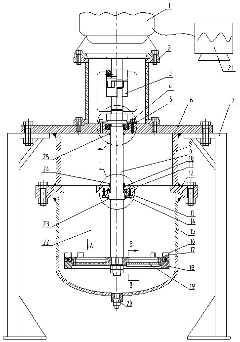
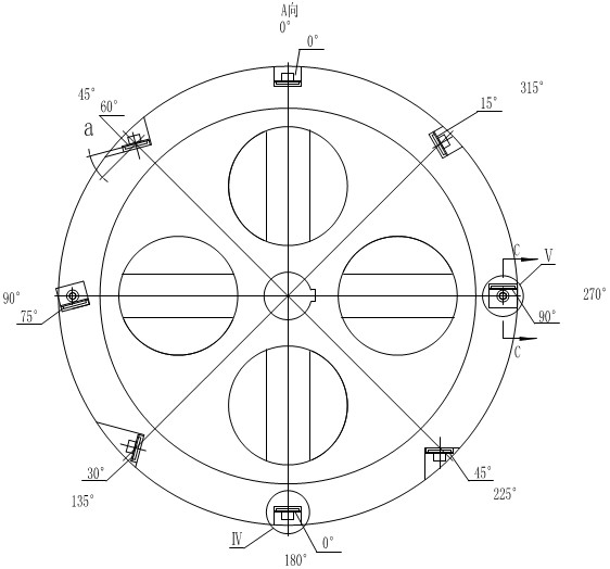
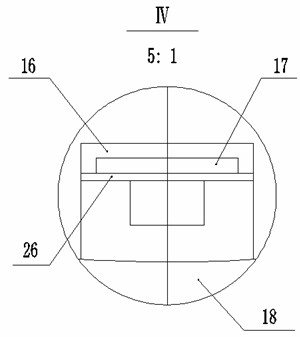
[0025] Such as figure 1 As shown, the present invention includes a slurry tank 15, a lower mounting plate 12, an upper mounting plate 6, a deep groove ball bearing 4, a turntable 18, a test piece mounting plate 16, eight test pieces 17, a stirring blade 19, and a connecting sleeve 8 , stirring shaft 9, the first high-speed dust-proof ring 10, the second high-speed dust-proof ring 14, angular contact ball bearing 11, angular contact ball bearing cover plate 13, bell housing 2, frequency conversion motor 1, plum-shaped elastic coupling 3. Plug 20, frequency converter 21, fluid medium 22, first water seal 23, second water seal 25, third water seal 24; frequency converter 21 and frequency conversion motor 1 are connected by cables, and frequency conversion motor 1 is connected through four The evenly distributed bolt connection is fixed vertically on the upper end of the b...


PUM

PropertyMeasurementUnit
heightaaaaaaaaaa
widthaaaaaaaaaa
thicknessaaaaaaaaaa

Abstract

The invention discloses a rotary type liquid-solid two-phase flow erosive wear test device. A variable frequency motor is arranged at the upper end of a bell-shaped cover; a stirring shaft passes through an upper installation plate and a lower installation plate from bottom to top and is connected with a shaft head of the variable frequency motor through a coupler; the tail end of the stirring shaft passes through a rotary table; eight test pieces are uniformly arranged in eight opened grooves which are arranged at the edge of the rotary table at intervals; the upper installation plate and the lower installation plate are welded by a coupling sleeve; a slurry tank filled with a fluid medium is connected and fixed with the lower installation plate; and stirring blades are uniformly distributed and fixed inside the rotary table in a manner of forming a 15-degree angle with the horizontal plane. The test device can realize testing to the erosive wear characteristic of different materialsby utilizing the characteristic that the variable frequency motor generates different rotation speeds so as to obtain the functional relations between the erosive wear rate and the variables such as material characteristics, rotation speeds and impact angles, therefore the test device can provide important data support for erosive wear prediction of engineering actual pipelines and is applicable to research on safety guarantee technologies such as erosive wear predication and optimal design of pipe fittings such as multiple-phase flow pipelines and valves in the fields of petrochemical industry and coal chemical industry.

Description

technical field [0001] The invention relates to a scouring wear test device, in particular to a rotary liquid-solid two-phase flow scouring wear test device used in industrial production. Background technique [0002] Fluid pipelines are special equipment for transporting fluids under certain pressure. With the development of the economy, fluid pipelines have become one of the five transportation modes along with highways, railways, water transportation and aviation, and are widely used in the transportation of various fluid materials in crude oil, natural gas, tap water, urban liquefied gas and process industries. [0003] The study found that pipeline failures come in various forms and complex mechanisms, such as material defects, corrosion, wear, and external force damage. Among them, wear failure caused by erosion and wear damage is the most widespread and common damage form in pipeline systems. Erosion wear damage has obvious locality, suddenness, and risk, especially ...

Claims


Application Information

Patent Timeline
Patent Type & Authority Applications(China)
IPC IPC(8): G01N17/00G01N5/04
CPCY02P20/10
Inventor 偶国富章利特饶杰叶健金浩哲
Owner HANGZHOU FURUDE TECH
Why Eureka
Try Eureka