Detection device and monitoring system for soil relative humidity and soil fertility change

A detection device, a technology of relative humidity, applied in the direction of material capacitance, etc., can solve the problems of large error, soil destructiveness, and long time required to measure soil moisture.

Inactive Publication Date: 2012-07-11
BEIJING ANSAIBO TECH
View PDF7 Cites 54 Cited by
  • Summary
  • Abstract
  • Description
  • Claims
  • Application Information

AI Technical Summary

Problems solved by technology

Among them, the weighing and drying method is the basic method for measuring soil moisture, and its measurement accuracy is high. The required soil drills and ovens are conventional equipment, which are relatively easy to meet. At the same time, it is also the basis for other methods of calibration and is often used for inspection The advantages and disadvantages of other measurement methods; however, the drying method requires a lot of workload in field sampling, and it takes a long time to measure soil moisture with oven drying, which is destructive to the soil and is not convenient for long-term fixed-point continuous monitoring
The neutron method overcomes some shortcomings of the drying method. It does not need to take soil, does not destroy the structure of the soil, and can realize fixed-point continuous observation of soil moisture, but neutrons have potential radiation. The error in moisture measurement is relatively large, on-site calibration is required, and the equipment is expensive
Although the resistance method has been born for a long time, it is still widely used in the measurement of soil moisture. The sensor components used in the resistance method are ...

Method used


Image

  • Detection device and monitoring system for soil relative humidity and soil fertility change
  • Detection device and monitoring system for soil relative humidity and soil fertility change
  • Detection device and monitoring system for soil relative humidity and soil fertility change

Examples


Embodiment Construction

[0030] The principles and features of the present invention are described below in conjunction with the accompanying drawings, and the examples given are only used to explain the present invention, and are not intended to limit the scope of the present invention.

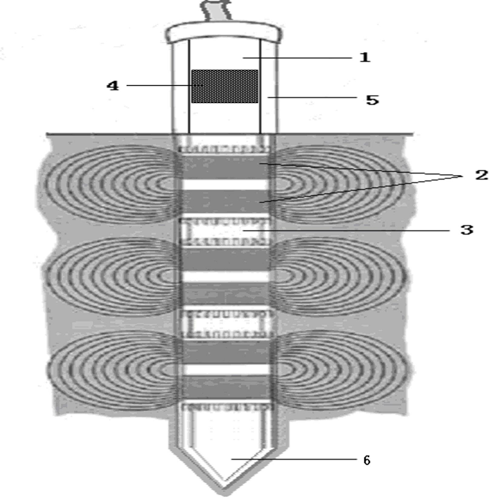
[0031] An embodiment of the present invention provides a detection device for changes in relative soil humidity and soil fertility, image 3 It is a structural diagram of the detection device in the embodiment of the present invention, such as image 3 As shown, in the embodiment of the present invention, the detection device includes a cylindrical body 1, a capacitive sensor 2 arranged on the cylindrical body 1 to detect the soil, and a frequency generator 4 for generating the operating frequency of the capacitive sensor 2 , different resonant frequencies are generated by the frequency generator 4 so that the same capacitive sensor 2 detects changes in soil relative humidity and soil fertility, and the capacitive d...


PUM


Abstract

The invention relates to a detection device and a monitoring system for soil relative humidity and soil fertility change. The detection device comprises a columnar body, a capacitive sensor which is arranged on the columnar body and is used for detecting soil, a frequency generator which is used for generating the working frequency of the capacitive sensor, a processing circuit which is used for processing detection signals obtained by the capacitive sensor and an anticorrosive shell which is arranged outside the capacitive sensor and the processing circuit, wherein different resonant frequencies can be generated through the frequency generator to enable the same capacitive sensor to detect the soil relative humidity and the soil fertility change. The soil relative humidity and the soil fertility can be monitored through the detection device which is buried in the soil for a long term, the parameters of the soil at different depths can be monitored at the same time and therefore effective guidance parameters are provided for fine management in the crop growth process.

Description

technical field [0001] The invention relates to soil detection technology, in particular to a detection device and a monitoring system for changes in soil relative humidity and soil fertility. Background technique [0002] "Soil" refers to the loose material layer covering the earth's land surface, which has the characteristics of fertility and can grow green plants. It is composed of various granular minerals, organic substances, water, air, microorganisms, etc. They are interconnected and mutually Restriction, providing the necessary living conditions for crops, is the material basis of soil fertility. The soil humidity determines the water supply status of crops. When the soil humidity is too low, the soil will be dry, and photosynthesis cannot be carried out normally, thereby reducing the yield and quality of crops, and even leading to wilting and death of crops when there is severe water shortage; When the soil humidity is too high, it will deteriorate the soil aeratio...

Claims


Application Information

Patent Timeline
IPC IPC(8): G01N27/22
Inventor 詹姆斯・刘
Owner BEIJING ANSAIBO TECH
Why Eureka
Try Eureka