Real-time on-off times recording device for relay in matrix switch module and method for realizing on-off times recording by employing same

A matrix switch and real-time recording technology, which is applied to the components of electrical measuring instruments, measuring devices, instruments, etc., can solve the problems of relay damage and increase the electrical service life of relays in matrix switches, so as to reduce the probability of damage and ensure continuous Stability and the effect of prolonging the electrical service life

Inactive Publication Date: 2012-07-11
HARBIN INST OF TECH
View PDF3 Cites 6 Cited by
  • Summary
  • Abstract
  • Description
  • Claims
  • Application Information

AI Technical Summary

Problems solved by technology

[0004] The purpose of the present invention is to solve the problem that the probability of damage to the relay increases sharply and the electrical service life of the relay in the matrix switch is short a

Method used


Image

  • Real-time on-off times recording device for relay in matrix switch module and method for realizing on-off times recording by employing same
  • Real-time on-off times recording device for relay in matrix switch module and method for realizing on-off times recording by employing same
  • Real-time on-off times recording device for relay in matrix switch module and method for realizing on-off times recording by employing same

Examples


Example Embodiment

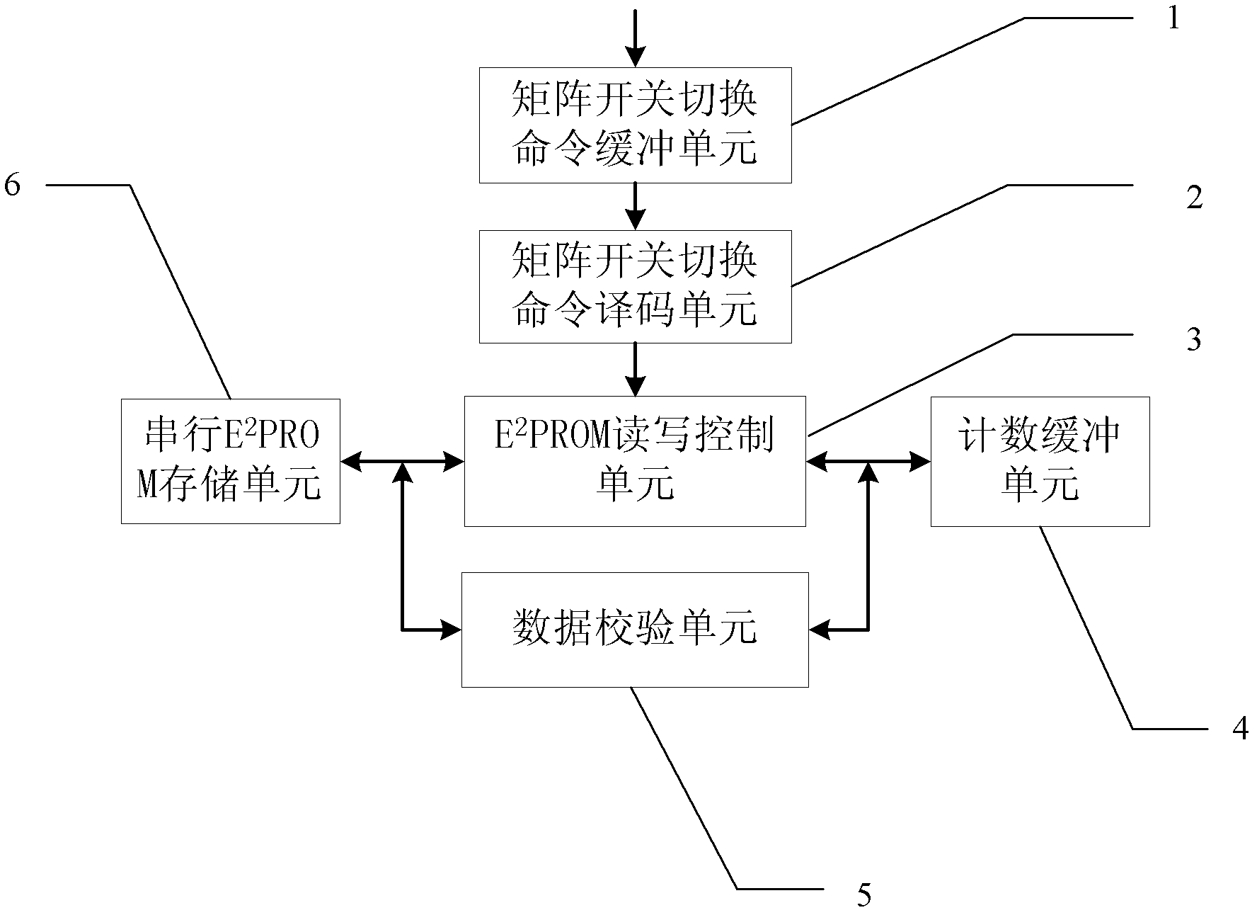
[0016] DETAILED DESCRIPTION OF THE PREFERRED EMBODIMENT 1. The real-time recording device for relay on / off times in the matrix switch module described in this embodiment includes a matrix switch switching command buffer unit 1, a matrix switch switching command decoding unit 2, E 2 PROM read and write control unit 3, count buffer unit 4, data verification unit 5 and serial E 2 PROM storage unit 6, described matrix switch switching command buffer unit 1 is a first-in-first-out memory,

[0017] The matrix switch switching command input terminal of the matrix switch switching command decoding unit 2 is connected to the switching command output terminal of the buffer unit 1, and the relay number output terminal of the matrix switch switching command decoding unit 2 is connected to E 2 The relay number input terminal of PROM read-write control unit 3, the E 2 The serial data read-write port of PROM read-write control unit 3 connects serial E 2 The serial data read and write port ...

Example Embodiment

[0018] Embodiment 2. The difference between this embodiment and Embodiment 1 is that the matrix switch switching command buffer unit 1 is a storage unit with a depth of 2×N and a width of N, and the matrix switch switching command buffer unit 1 is used for The executed matrix switch switching command is cached, wherein, N is equal to the number of rows of relays in the matrix switch module.

Example Embodiment

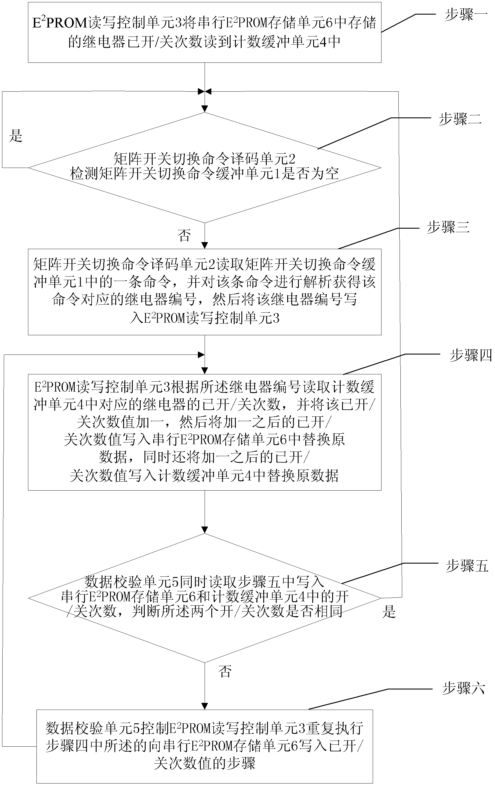
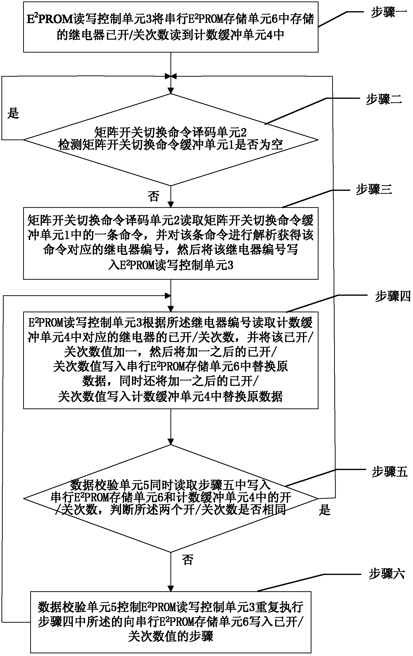
[0019] Specific embodiment three, described in this embodiment is to adopt the method for recording the number of times of on / off times of the relay in the matrix switch module described in the specific embodiment one described in the real-time recording device of on / off times, and it comprises the following steps:

[0020] Step one, E 2 PROM read and write control unit 3 will serial E 2 The on / off data of the relay stored in the PROM storage unit 6 is read in the counting buffer unit 4, and the on / off data of the relay includes the relay number and the corresponding on / off times of each number;

[0021] Step 2, the matrix switch switching command decoding unit 2 detects whether the matrix switch switching command buffer unit 1 is empty, until the switch switching command buffer unit 1 is non-empty, step 3 is performed;

[0022] Step 3, the matrix switch switching command decoding unit 2 reads a command in the matrix switch switching command buffer unit 1, and analyzes the co...


PUM


Abstract

The invention relates to a real-time on-off times recording device for a relay in a matrix switch module, and a method for realizing on-off times recording by employing same. The invention solves the problems that the probability of damage of the relay rises sharply along with the increase of service time, and the electrical life of the relay in the matrix switch is limited. The real-time on-off times recording device comprises a matrix switch switching command buffering unit, a matrix switch switching command decoding unit, an E2PROM reading-writing control unit, a counting buffering unit, a data verification unit and a serial E2PROM memory unit, wherein the matrix switch switching command buffering unit is a first-in-first-out memory. The serial number of the relay executing on-off actions is decoded by analyzing the switch switching command, and the on-off times of the relay is stored in the serial E2PROM memory unit. The device and the method are suitable for the filed of automatic testing.

Description

technical field [0001] The invention relates to a real-time recording device for on / off times of relays in a matrix switch module and a method for recording on / off times by using the device, belonging to the field of automatic testing. Background technique [0002] The matrix switch is the center of signal transmission and distribution in the automatic test system. With the help of different configurations of the matrix switch system, the limited resources of the automatic test system can be fully utilized to realize the flexible use of various detection and excitation signals. Therefore, the reliability of the matrix switch module Will directly affect the stability of the automatic test system. [0003] Matrix switch instruments in automatic test systems usually use relays as matrix switches for switching signals, however, the electrical life of relay matrix switches is limited, generally 10 5 Second-rate. As the number of uses increases, the probability of relay damage i...

Claims


Application Information

Patent Timeline
IPC IPC(8): G01R1/00
Inventor 刘兆庆乔立岩张毅刚杜威达陈长春彭喜元
Owner HARBIN INST OF TECH
Why Eureka
Try Eureka