Optical fiber plug

An optical fiber plug and plug technology, which is applied in the field of optical communication, can solve the problems of difficult adaptation of the optical fiber plug, difficulty in assembly, influence of the strength of the optical fiber plug, etc., and achieve the effects of easy production and manufacturing, convenient connection and coordination, and convenient assembly.

Active Publication Date: 2012-07-11
SHENZHEN EPLU SCI TECH
6 Cites 15 Cited by

AI-Extracted Technical Summary

Problems solved by technology

When the size of the optical fiber connector is reduced, the structure of the existing optical fiber plug is difficult to adapt to, especially the assembly is difficult. In addition, in o...

Method used

As shown in Figure 1 to Figure 4, it is the first embodiment of the optical fiber plug of the present invention, the volume of this optical fiber plug is about 1/2 of the existing LC optical fiber plug, the adapter of the same size can be inserted into two double the number of optical fiber plugs in this embodiment, the connection density is doubled. The optical fiber plug includes a front housing 100 and a rear housing 200, and the front housing 100 and the rear housing 200 are fixedly connected.
In order to facilitate the assembly of the optical fiber plug and the processing of the rear housing, a side of the rear housing 200 has a window 202, and the rear housing 200 also includes a cover plate 220 covering the window 202. Due to the existence of the window, the rear housing 200 The housing 200 is easier to injection mold, and the mold demoulding is more convenient. On the other hand, it can also be used as an observation window, which can easily observe the cooperation between the optical fiber and the tailstock 320 when the tail end of the rear housing 200 is loaded. The tail end of the rear housing 200 is provided with a tail pipe 230, and the optical fiber 400 extends into the rear housing 200 through the tail pipe 230, and extends into the ceramic ferrule 310 through the tailstock 320. In this embodiment, the tail pipe 230 is a metal pipe, the front end and rear end of the tail pipe 230 are respectively provided with ring grooves 231, 232, the front end of the tail pipe 230 is embedded in the tail end of the rear housing 200, and it is molded together with the tailstock 200, and the ring groove 231 is embedded in the rear shell 200 to ensure the reliability of the connection between the two; the rear end of the tail pipe 230 is covered with an aluminum tube 240, and the aluminum tube 240 is pressed with a ring groove 241 corresponding to the ring groove 232 at the rear end of the tail pipe 220 , the aramid fiber of the optical fiber 400 is laminated between the aluminum tube 240 and the tail tube 230 , and the aluminum tube 240 is also covered with a heat shrinkable sleeve 250 to ensure reliable fixing of the optical fiber 400 .
In the optical fiber plug of the present invention, the front housing accommodates the ferrule assembly, and the rear housing has a window to ensure that the optical fiber plug has sufficient accommodation space and micro-bending space when the volume is reduced. In addition, the optical fiber plug of the present invention The structure of the optical fiber plug also facilitates the processing and assembly of the components of the optical fiber plug.
Referring to Fig. 6, when the optical fiber plug of the present invention is matched with the adapter 500, it is realized by fastening the outside of the adapter 500, specifically, the buckle 501 is set on the outer wall of the adapter 500, and the optical fiber plug is provided with a corresponding The fastening part of the adapter 500 realizes the reliable insertion of the optical fiber plug and the adapter 500. In this way, the existing internal fastening structure is changed to an external fastening structure, which can effectively use the internal space of the adapter 500 and avoid occupying the space of the optical fiber plug. For the optical fiber plug, specifically, a snap-fit ​​arm 260 is provided on the rear housing 200, a connecting piece 261 extends from the middle of the snap-fit ​​arm 260, and a sleeve 262 extends from the connecting pie...

Abstract

The invention relates to an optical fiber plug. The optical fiber plug comprises a front housing and a rear housing, and is characterized in that the front housing and the rear housing are detachably connected, a buckling arm which is used for being buckled with an optical fiber adapter is movably connected on the rear housing, and an elastic element is arranged between the buckling arm and the rear housing. According to the optical fiber plug disclosed by the invention, the front housing is detachably connected with the rear housing, and optical fiber connection is convenient in assembly and convenient for production and manufacturing; and the buckling arm which is buckled with the adapter is movably connected on the rear housing so as to facilitate connection and matching between the optical fiber plug and the adapter.

Application Domain

Coupling light guides

Technology Topic

EngineeringOptical fiber cable

Image

  • Optical fiber plug
  • Optical fiber plug
  • Optical fiber plug

Examples

  • Experimental program(1)

Example Embodiment

[0032] In order to have a clearer understanding of the technical features, objectives and effects of the present invention, the specific embodiments of the present invention will now be described in detail with reference to the accompanying drawings.
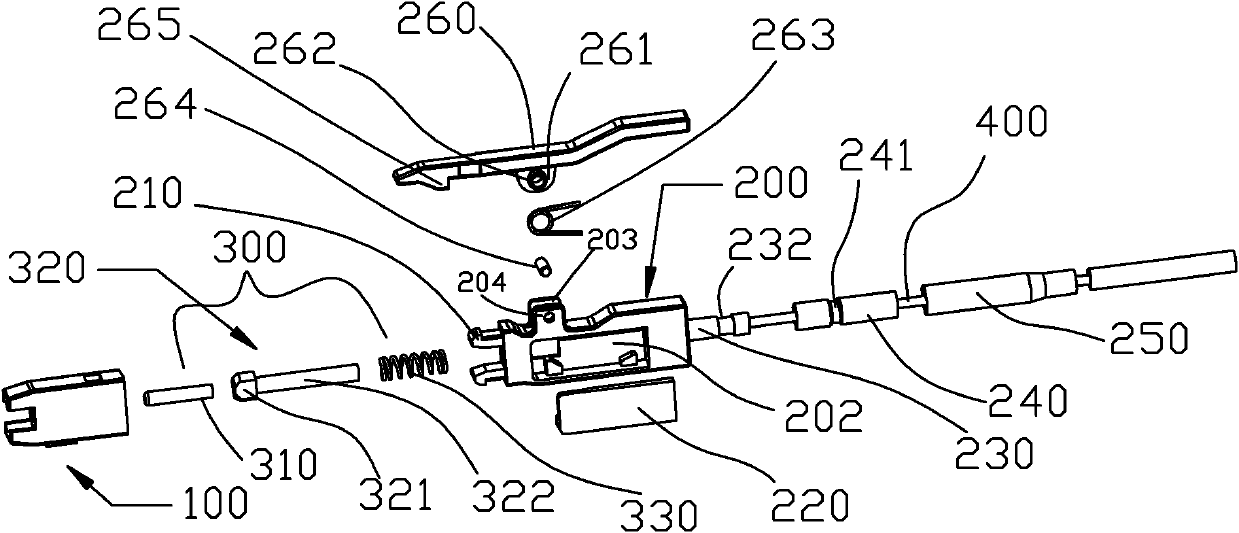
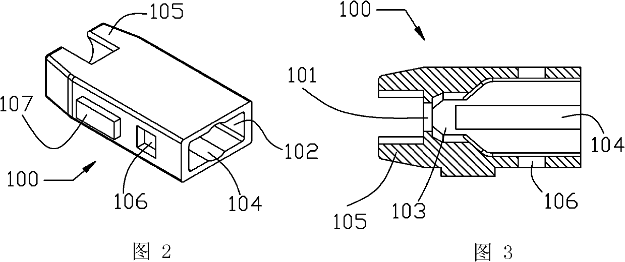
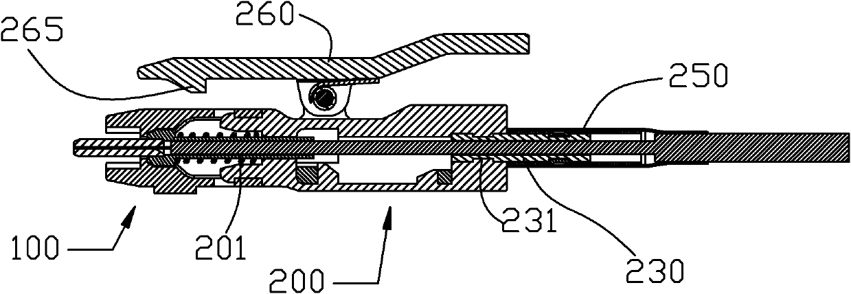
[0033] Such as Figure 1 to Figure 4 Shown is the first embodiment of the optical fiber plug of the present invention. The volume of the optical fiber plug is about 1/2 of the existing LC optical fiber plug. The adapter of the same size can insert twice the number of the optical fiber plug of this embodiment. , The connection density is doubled. The optical fiber plug includes a front housing 100 and a rear housing 200, and the front housing 100 and the rear housing 200 are fixedly connected.
[0034] The front housing 100 is provided with a first through hole 101, and the rear end of the front housing 100 is provided with an opening 102. The front housing 100 contains a ferrule assembly 300. The ferrule assembly 300 includes a ceramic ferrule 310 and a metal tail. The seat 320 and the tail seat 320 are made of metal and include a head 321 and a cylindrical section 322 connected to the head 321. The ceramic ferrule 310 is inserted into the head 321 of the tail seat 320, and the ferrule assembly also includes The spring 330 on the cylindrical section 322, the ceramic ferrule 310 extend out of the front housing 100 through the first through hole 101, and the front end of the inner cavity of the front housing 100 is provided with a recess adapted to the shape of the head 321 of the tailstock 320 The pit 103, the head 321 is inserted into the pit 103. The inner wall of the front housing 100 is provided with two opposite arc-shaped relief grooves 104 that are adapted to the spring 330. The existence of the relief grooves 104 can also facilitate the assembly of the ferrule assembly 300 into the front housing 100 . In order to protect the ceramic ferrule 310, two opposite flanges 105 extend forward at the front end of the front housing 100, and the ceramic ferrule 310 is located between the two flanges 105, which can protect the ceramic ferrule 310. effect. In order to facilitate the cooperation between the optical fiber plug and the optical fiber adapter, a guiding protrusion 107 is provided on the lower side of the front housing 100, and the same guiding groove is provided on the inner wall of the optical fiber adapter.
[0035] In this embodiment, the front housing 100 and the rear housing 200 are fixedly connected by buckling. Specifically, two undercuts 210 extend forward from the front end of the rear housing 200. The buckle 106 matched with the buckle 210 is inserted into the front housing 100 and the undercut 210 is buckled into the buckle 106 to realize a fixed connection between the front housing 100 and the rear housing 200.
[0036] The front end of the rear housing 200 is provided with a second through hole 201, the rear end of the tailstock 320 extends into the second through hole 201, one end of the spring 330 abuts on the front end of the rear housing 200, and the other end abuts on the tail. The front end of the seat 320 is formed on the boss formed by the head 321; since the tail seat 320 is made of metal, its cylindrical section 322 is inserted into the second through hole 201, and the second through hole 201 is used to limit the optical fiber The structure of the plug also plays a strengthening role, so that the front end force is no longer concentrated on the connection between the front housing 100 and the rear housing 200, which improves the strength of the optical fiber plug and reduces the size of the optical fiber plug. The wall thickness of the body has been reduced, but the strength of the entire optical fiber plug can still meet the needs.
[0037] In order to facilitate the assembly of the optical fiber plug and the processing of the rear housing, a window 202 is opened on one side of the rear housing 200. The rear housing 200 also includes a cover 220 covering the window 202. Due to the existence of the window, the rear housing 200 Injection molding is easier, and mold demolding is more convenient. On the other hand, it can also be used as an observation window to conveniently observe the fit of the optical fiber with the tailstock 320 when the optical fiber is inserted from the tail end of the rear housing 200. The tail end of the rear housing 200 is provided with a tail pipe 230. The optical fiber 400 extends from the tail pipe 230 into the rear housing 200, and then extends into the ceramic ferrule 310 through the tailstock 320. In this embodiment, the tail pipe 230 is a metal pipe. The front and rear ends of the tail pipe 230 are respectively provided with ring grooves 231 and 232. The front end of the tail pipe 230 is inserted into the tail end of the rear housing 200, which is formed in-mold together with the tailstock 200. The ring groove 231 is embedded in the rear housing 200 to ensure the reliability of the connection between the two; the rear end of the tail pipe 230 is covered with an aluminum tube 240, and the aluminum tube 240 is pressed with a ring groove 241 corresponding to the ring groove 232 at the rear end of the tail pipe 220 The aramid fiber of the optical fiber 400 is laminated between the aluminum tube 240 and the tail tube 230, and the aluminum tube 240 is also covered with a heat shrinkable tube 250 to ensure the reliable fixation of the optical fiber 400.
[0038] See Image 6 When the optical fiber plug of the present invention is matched with the adapter 500, it is realized by buckling on the outside of the adapter 500. Specifically, a buckle 501 is provided on the outer wall of the adapter 500, and a corresponding buckle is provided on the optical fiber plug to realize the optical fiber The plug can be reliably inserted into the adapter 500. This method changes the existing internal buckling structure to an external buckling structure, which can effectively utilize the internal space of the adapter 500 and avoid occupying the space of the optical fiber plug. For the optical fiber plug, specifically, a buckling arm 260 is provided on the rear housing 200, a connecting piece 261 extends from the middle of the buckling arm 260, and a sleeve 262 extends from the connecting piece 261, and the sleeve 262 is covered with Torsion spring 263, two lugs 203, 204 extend from the upper part of the rear housing 200, the connecting piece 261 is located between the two lugs 203, 204, the pin 264 passes through the lugs 203, 204 and the connecting piece 261 to realize the buckling arm The 260 is connected to the rear housing 200 in rotation, and when the adapter 500 is buckled, the torsion spring 263 presses the buckle portion 265 at the front end of the buckling arm 260 against the buckle position 501 of the adapter 500.
[0039] The assembly of the optical fiber plug of the present invention is relatively flexible. One assembly method is to first assemble the ceramic ferrule assembly 300 and then install it into the front housing 100, and then the front housing 100 and the rear housing 200 are buckled together, and then the rear housing The tail tube 230 of 200 penetrates the optical fiber 400 so that the optical fiber 400 enters the ceramic ferrule 310 through the tailstock 320. The bare fiber after the sheath is stripped is inserted into the ceramic ferrule 310, and then the aluminum tube 240 is pressed on the tail tube 230 And put on the heat shrinkable tube 250. In another assembly method, the optical fiber is first inserted through the tail tube 230 and out of the second through hole 201, and the optical fiber is inserted into the tail stock 320 covered with the spring 330 and extended into the ceramic ferrule 310. After the ceramic ferrule is assembled, the front housing 100 and the rear housing 200 are assembled together.
[0040] Such as Figure 5 Shown here is the second embodiment of the optical fiber plug of the present invention. The difference from the first embodiment is that in this embodiment, the front housing 100 and the rear housing 200 are connected by a clamp 600, specifically the rear housing Two opposite positioning blocks 205 extend forward from the front end of the body 200. The positioning blocks 205 are inserted into the front housing 200 to perform positioning. Then, the clamp 600 is wrapped around the rear end of the front housing 100 and the rear housing. The front end of the body 200. The clamp 600 includes a side wall 610 and two buckle arms 620 perpendicular to the side walls at both ends of the side wall. The buckle arms 620 are provided with notches 621. The front housing 100 and the rear housing 200 are respectively provided with the notches 621 The limiting blocks 108 and 206 are stuck in the gap 611. The other structure of the optical fiber plug of this embodiment is the same as that of the first embodiment, and will not be repeated. It should be understood that the front housing 100 and the rear housing 200 may also be fixedly connected in any other suitable manner.
[0041] Figure 7 to Figure 10 These are schematic diagrams of the third to sixth embodiments of the optical fiber plug of the present invention. The basic structures of the optical fiber plugs of the four embodiments are the same, and the only difference is that the buckling arms of the optical fiber plug are different.
[0042] in Figure 8 In the third embodiment shown, the tail end of the buckling arm 260 is connected to a pull ring 271, and the pull ring 271 is slidably connected to the rear housing. When the pull ring 271 is pulled backward, the tail end of the buckle arm 260 is When pressed down, the front end of the buckling arm 260 is raised, and the buckling arm 260 is released from the adapter.
[0043] in Picture 9 In the fourth embodiment, the tail end of the buckling arm 260 is connected with a pull ring 272. The difference between the pull ring 272 and the third embodiment is that the pull ring 272 is directly connected to the tail end of the buckling arm 260. Pressing and pulling the tab 272 backward can release the buckling arm 260 from the adapter.
[0044] In the fifth embodiment shown in 10, the tail end 266 of the buckling arm 260 is tilted upward, so that the buckling arm 260 can be buckled by pressing. While in Picture 10 In the sixth embodiment shown, the tail end 266 of the buckling arm 260 is tilted downward, which is beneficial to save space, and the pressing of the buckling arm 260 needs to be performed with the help of a certain tool.
[0045] Picture 11 with Picture 12 Two forms of buckling arms are shown again, in Picture 11 A hole 267 is provided at the end of the middle buckling arm 260. With the aid of a tool inserted in the hole 267, the buckling arm 260 can be conveniently manipulated to release the buckling arm 260 from the adapter. While in Picture 12 , A notch 268 is provided at the end of the buckling arm 260, and the buckling arm 260 can also be hooked or stuck in the cover notch 268 with the help of a tool to release the buckling arm 260 from the adapter. This type of buckling arm requires certain tools, but it can avoid accidentally touching other adjacent optical fiber plugs.
[0046] In the optical fiber plug of the present invention, the front housing contains the ferrule assembly, and the rear housing has a window to ensure that the optical fiber plug has sufficient storage space and slight bending space when the volume is reduced. In addition, the optical fiber plug of the present invention has The structure also facilitates the processing and assembly of the components of the optical fiber plug.
[0047] The embodiments of the present invention are described above with reference to the accompanying drawings, but the present invention is not limited to the above-mentioned specific embodiments. The above-mentioned specific embodiments are only illustrative and not restrictive. Those of ordinary skill in the art are Under the enlightenment of the present invention, many forms can be made without departing from the purpose of the present invention and the protection scope of the claims, and these are all within the protection of the present invention.

PUM

no PUM

Description & Claims & Application Information

We can also present the details of the Description, Claims and Application information to help users get a comprehensive understanding of the technical details of the patent, such as background art, summary of invention, brief description of drawings, description of embodiments, and other original content. On the other hand, users can also determine the specific scope of protection of the technology through the list of claims; as well as understand the changes in the life cycle of the technology with the presentation of the patent timeline. Login to view more.

Similar technology patents

Backlight module and display device

Owner:AU OPTRONICS (SUZHOU) CORP LTD +1

Keyboard with holder

Owner:SHENZHEN DOKING TECH CO LTD

Lens module group assembling system and method of use thereof

InactiveCN101290385AEasy to assemble
Owner:HONG FU JIN PRECISION IND (SHENZHEN) CO LTD +1

Classification and recommendation of technical efficacy words

  • Easy to assemble
  • Easy to manufacture

Electric pressure cooker

Owner:FOSHAN SHUNDE MIDEA ELECTRICAL HEATING APPLIANCES MFG CO LTD +1

Novel ceiling mounting structure

Owner:上海西蒙铝业有限公司

Standard Bailey truss assembling type jacking formwork system

ActiveCN103669832AEasy to assembleadaptable
Owner:NO 1 CONSTR ENG CO LTD OF CHINA CONSTR THIRD ENG BUREAU CO LTD

Electric connector and assembling method thereof

Owner:DONGGUAN TECONN ELECTRONICS TECH CO LTD
Why Eureka
Try Eureka