
High-precision focusing device used for space optical remote sensing instrument

A space optical remote sensing, high-precision technology, applied in the field of space remote sensing, can solve the problems of difficult manufacturing, long-life lubrication of space cold welding, large influence on the machining accuracy of precision transmission parts, etc. compact effect

Active Publication Date: 2012-07-11
SHANGHAI INST OF TECHNICAL PHYSICS - CHINESE ACAD OF SCI
View PDF4 Cites 30 Cited by
  • Summary
  • Abstract
  • Description
  • Claims
  • Application Information

AI Technical Summary

Problems solved by technology

[0003] At present, the focusing mechanism of domestic space high-sensitivity cameras mostly uses gear sets or cams for focusing. The accuracy of these two methods of focusing mechanisms is greatly affected by the machining accuracy of their transmission parts.
In particular, the processing requirements for the cam curve are higher, and the manufacturing is more difficult
At the same time, gear transmission or cam transmission are all sliding friction, and the problem of space cold welding and long-life lubrication are still difficult problems to be solved

Method used


Image

  • High-precision focusing device used for space optical remote sensing instrument
  • High-precision focusing device used for space optical remote sensing instrument

Examples


Embodiment Construction

[0028] Below in conjunction with accompanying drawing, a specific embodiment of the present invention is described in detail:

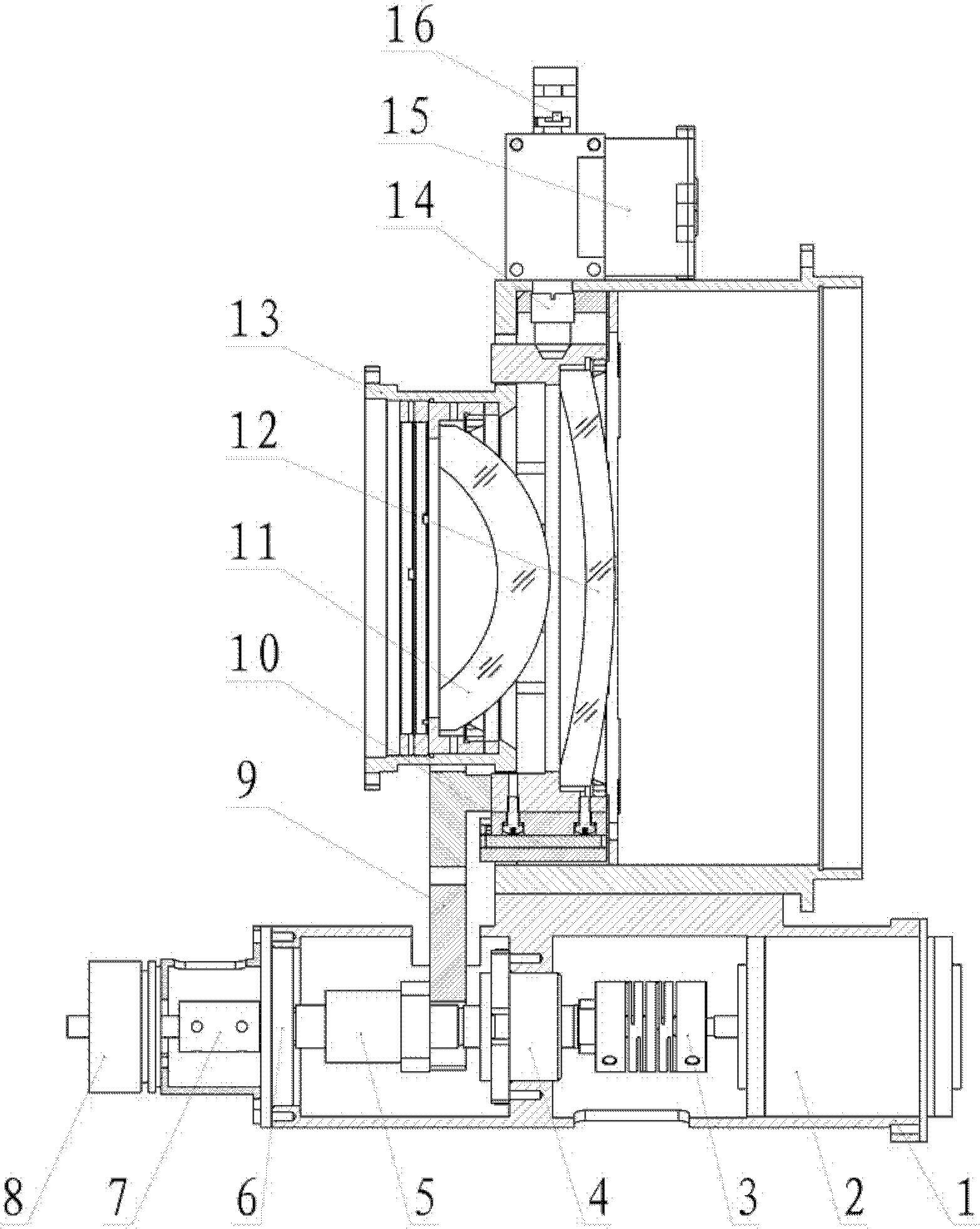
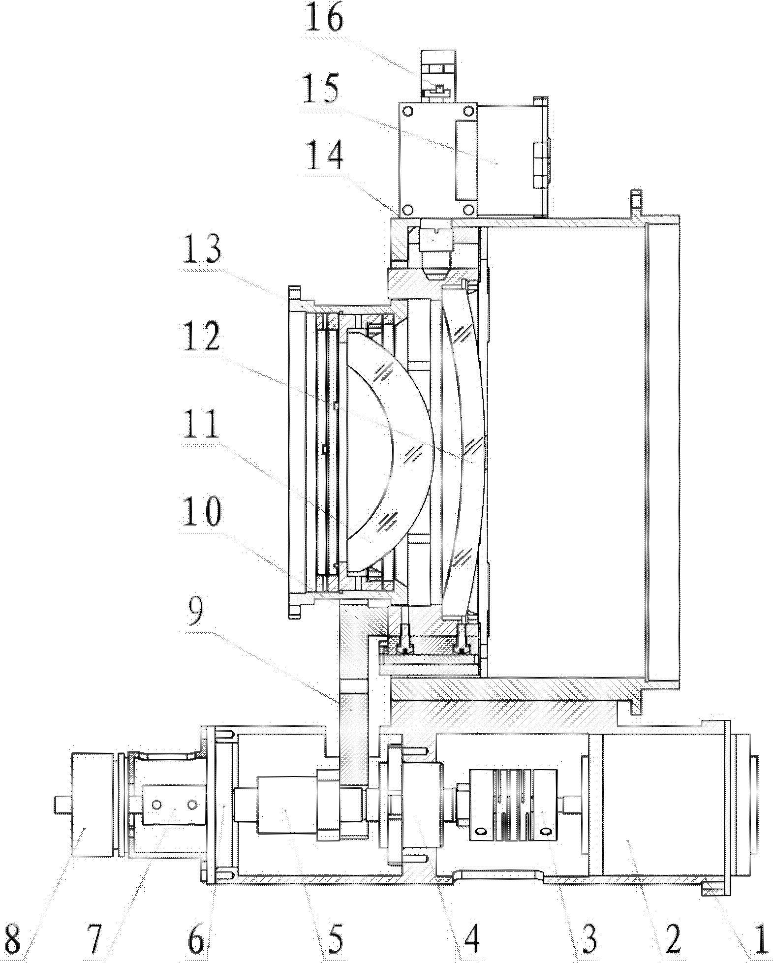
[0029] Such as figure 1 As shown, the focusing mechanism is installed in the focusing mechanism supporting tube 1 , and the fixed lens 11 and the focusing lens 12 are both installed in the lens supporting tube 13 . One end of the U-shaped focusing connecting frame 9 is installed on the nut seat of the precision ball screw 5, and the other end is fixed on the moving ring of the focusing lens. In order to facilitate the optical calibration of the entire optical system, it is necessary to ensure that the optical axis of the lens assembly is as consistent as possible with the mechanical axis of the lens support tube 13 . For this reason, in the design and processing process, ensure that the cylindricity of the two inner circles of the lens support tube 13, the focusing lens 12, and the fixed lens 11 are respectively less than 0.008mm, and the coaxiality ...


PUM


Abstract

The invention discloses a high-precision focusing device used for a space optical remote sensing instrument. The high-precision focusing device comprises two parts, namely a focusing mechanism and a locking mechanism, wherein the main parts of the focusing mechanism, namely a driving motor, a precision ball screw and a potentiometer, are all arranged in a support cylinder of the focusing mechanism; a fixed lens and a focusing lens are arranged in a lens support cylinder, and a focusing movement part and the focusing lens are connected by a focusing connecting frame. When the high-precision focusing device works, the ball screw changes the rotation movement of the driving motor into the linear movement, the focusing lens is driven to move along the axial direction by a high-precision linear sliding way, and the focusing position is controlled according to feedback signals of the potentiometer. In the device, the locking mechanism is used for locking the initial position of the focusinglens. The device of the invention can drive heavy-calibre optical elements, is good in movement stability, has accurate positioning precision and repeated positioning precision, and meets the demand of long-service-life focusing of a space remote sensing camera. In addition, the locking mechanism is adopted for fully ensuring the constant optimal ground image quality position.

Description

technical field [0001] The invention relates to the technical field of space remote sensing, in particular to a high-precision focusing device for space high-sensitivity optical remote sensing instruments. Background technique [0002] Space remote sensing instruments are different from ground optical instruments. They have to withstand mechanical environments such as shock, vibration, and overload during the launch phase. After the camera has experienced a series of harsh environments, the distance between the primary and secondary mirrors or lenses will change, resulting in a certain degree of deviation of the best focal plane, which will directly affect the imaging quality of the camera in severe cases. High-sensitivity optical remote sensing instruments are more sensitive to changes in the external environment. In order to ensure that the space camera can still have high imaging quality in harsh environments, it is necessary to actively correct the position of some optic...

Claims


Application Information

Patent Timeline
IPC IPC(8): G02B7/04G03B13/34
Inventor 陈洪达史婷婷郑庚刘晓华
Owner SHANGHAI INST OF TECHNICAL PHYSICS - CHINESE ACAD OF SCI
Learn More