
Method for testing diaphragm of illumining system of photoetching equipment

An illumination system and test light technology, which are applied in microlithography exposure equipment, photometric exposure devices using electrical radiation detectors, and photolithographic process exposure devices, etc., can solve problems such as inability to determine illumination pupil photodetectors, inaccuracy, etc. , to achieve the effect of improving the test accuracy

Inactive Publication Date: 2012-07-11
SHANGHAI MICRO ELECTRONICS EQUIP (GRP) CO LTD
View PDF4 Cites 4 Cited by
  • Summary
  • Abstract
  • Description
  • Claims
  • Application Information

AI Technical Summary

Problems solved by technology

Due to the inaccurate position of the photodetector, it is impossible to determine whether it is the shift of the illumination pupil itself or the inaccurate position of the photodetector.

Method used


Image

  • Method for testing diaphragm of illumining system of photoetching equipment
  • Method for testing diaphragm of illumining system of photoetching equipment
  • Method for testing diaphragm of illumining system of photoetching equipment

Examples


Embodiment Construction

[0031] Specific embodiments of the present invention will be described in detail below in conjunction with the accompanying drawings.

[0032] The object of the present invention is to provide a method for testing the pupil of an illumination system applied in lithography equipment, which is referred to as a pupil testing method for convenience of description below. The pupil testing method can accurately and completely measure the light intensity sampling data and the pupil position distribution in the pupil plane in the illumination system.

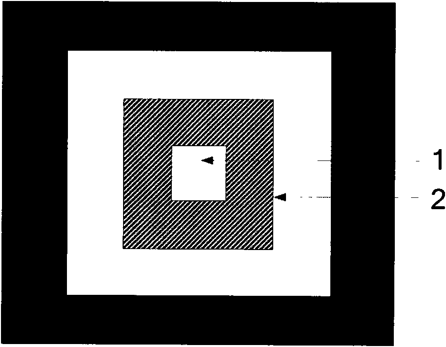
[0033] The present invention utilizes a special pupil test mask that can function as a diaphragm, and at least one aperture that can be used for position calibration and pupil test in the field of view is arranged on the mask, and the small aperture is calibrated by the boundary scan method. The center position of the aperture, and then perform an accurate pupil distribution test at this calibrated position. The specific implementation...


PUM


Abstract

The invention discloses a method for testing a diaphragm of an illumining system of photoetching equipment. The method comprises the steps of: 1, uploading a testing mask consisting of a test hole and measuring reference light intensity by using a photoelectric detector; 2, detecting the testing mask by using the photoelectric detector, and when a point at which the reference light intensity is 60-100% is detected, taking the point as an initial position point for determining border scanning; 3, detecting the border of the test hole by the photoelectric detector respectively, and taking the detected point at which the reference light intensity is 50% as a border point; 4, calculating the central point of the test hole according to the border point; and 5, carrying out stepping light intensity sampling on the test hole according to the centra point of test hole so as to complete diaphragm measurement.

Description

technical field [0001] The invention relates to the field of semiconductor integrated circuit equipment manufacturing, in particular to a method for testing the pupil of an illumination system of a lithographic equipment. Background technique [0002] Lithography equipment is a kind of equipment used in the manufacture of integrated circuits. The use of this equipment includes but is not limited to: integrated circuit manufacturing lithography equipment, liquid crystal panel lithography equipment, photomask marking equipment, MEMS (micro-electromechanical systems) / MOMS (micro-optical machine system) lithography equipment, advanced packaging lithography equipment, printed circuit board lithography equipment and printed circuit board processing equipment, etc. [0003] In the lighting system of lithography equipment, the quality of the lighting pupil has a great influence on the resolution, line width, focal depth, and the density deviation (IsoDense Bias) of graphics; the m...

Claims


Application Information

Patent Timeline
Patent Type & Authority Applications(China)
IPC IPC(8): G03F7/20G01J1/42
Inventor 宋平马明英
Owner SHANGHAI MICRO ELECTRONICS EQUIP (GRP) CO LTD
Learn More