
Method for manufacturing encapsulation structure for light-emitting diode

A technology of light-emitting diodes and packaging structures, which is applied in the direction of electrical components, circuits, semiconductor devices, etc., and can solve the problems affecting the uniformity of light output or color rendering of the packaging structure of light-emitting diodes, excessive deviation of the outside of the reflective cup or dispensing position, overflow of glue or packaging In order to improve the uniformity of light output and color rendering, prevent the formation of unevenness, and achieve the effect of precise movement and positioning

Inactive Publication Date: 2012-07-11
ZHANJING TECH SHENZHEN +1
View PDF3 Cites 5 Cited by
  • Summary
  • Abstract
  • Description
  • Claims
  • Application Information

AI Technical Summary

Problems solved by technology

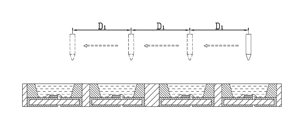
like figure 1 As shown, generally the movement of the glue needle in this dispensing process is controlled by inputting a fixed program in the glue dispenser, and the movement distance of the glue needle is often a preset value D 1 If the distance between the reflective cups on the substrate is inconsistent, it is easy to cause the glue to be dotted outside the reflective cup or the dispensing position is too biased, causing problems such as overflow of glue or uneven formation of the packaging layer, which will affect the uniformity of light output or the packaging structure of the light emitting diode. Color rendering

Method used


Image

  • Method for manufacturing encapsulation structure for light-emitting diode
  • Method for manufacturing encapsulation structure for light-emitting diode
  • Method for manufacturing encapsulation structure for light-emitting diode

Examples


Embodiment Construction

[0031] The present invention will be further described in detail below in conjunction with the accompanying drawings.

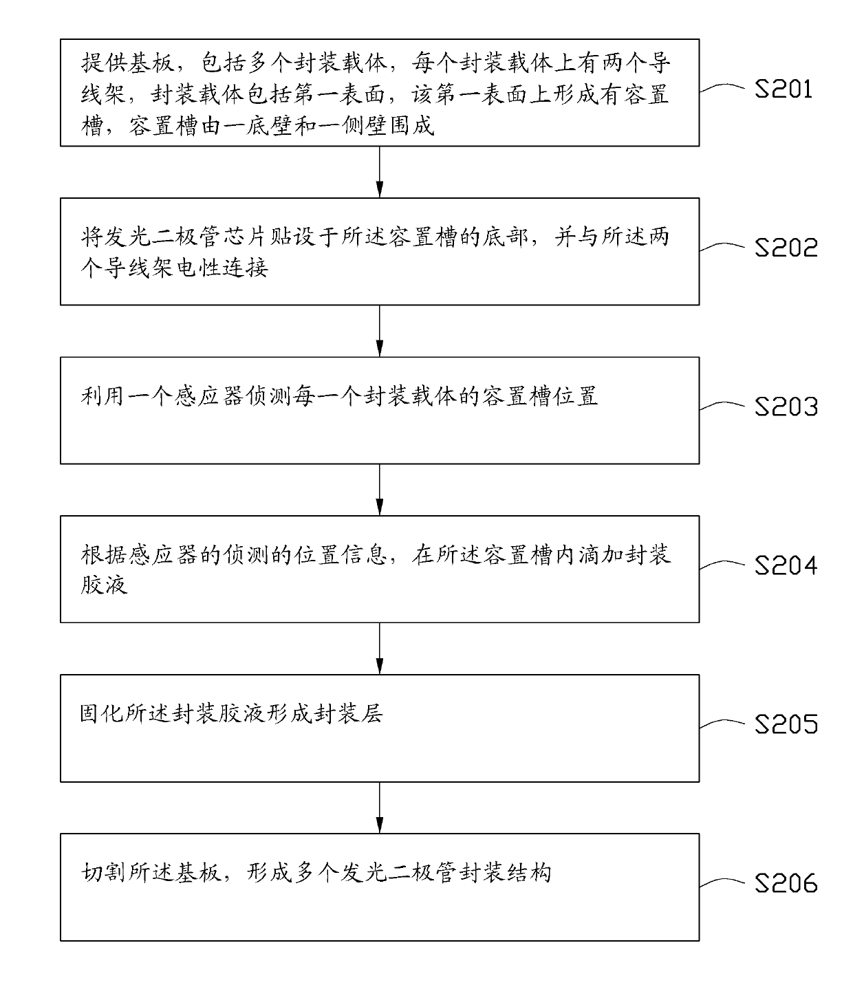
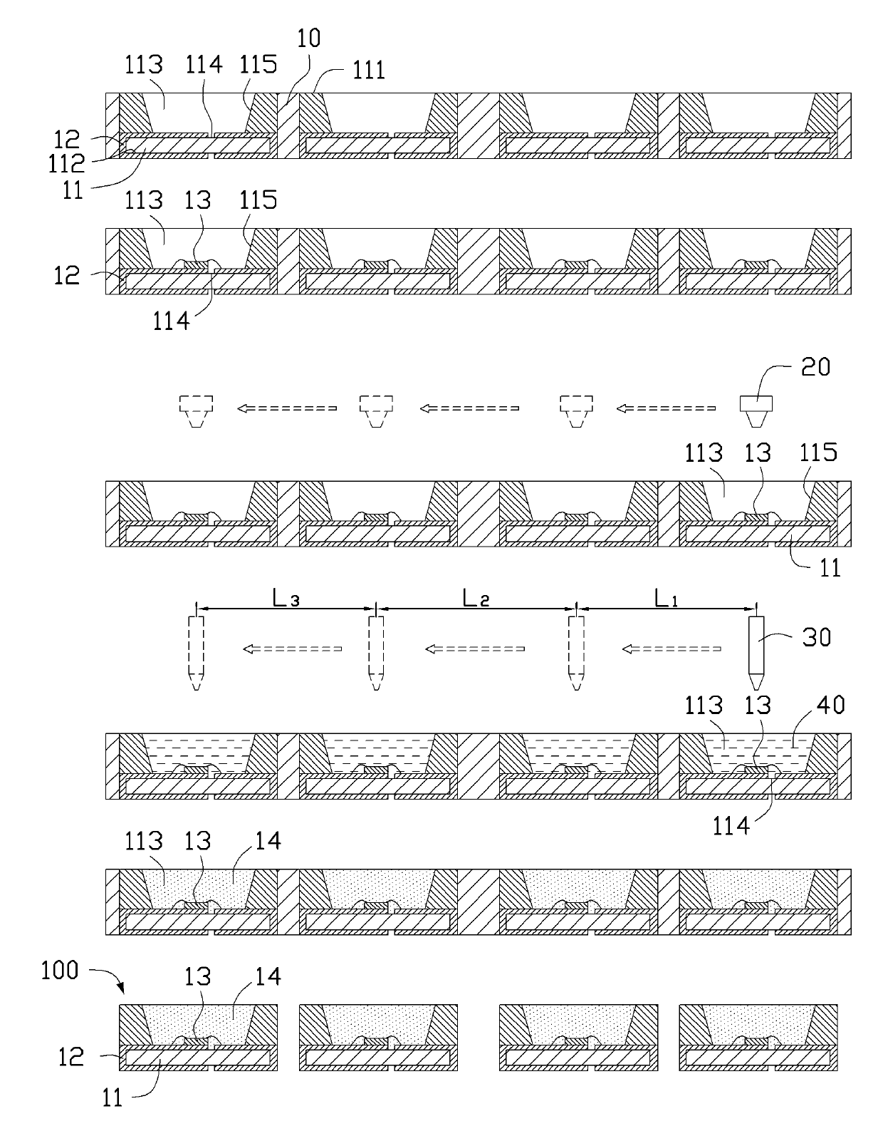
[0032] see figure 2 and image 3 A method for manufacturing a light emitting diode packaging structure provided in an embodiment of the present invention includes the following steps.

[0033] Step S201 : providing a substrate 10 . The substrate 10 includes a plurality of package carriers 11 , and each package carrier 11 has two lead frames 12 on it. The package carrier 11 includes a first surface 111 and a second surface 112 opposite to each other. An accommodating groove 113 is formed on the first surface 111 . The accommodating groove 113 is surrounded by a bottom wall 114 and a side wall 115 . The bottom wall 114 and the side wall 115 can be integrally formed or fixed by glue or the like. In this embodiment, the bottom wall 114 and the side wall 115 are integrally formed. The package carrier 11 can be made of high thermal conductivity and electrica...


PUM


Abstract

The invention relates to a method for manufacturing an encapsulation structure for a light-emitting diode, which comprises the following steps: providing a substrate, wherein the substrate comprises a plurality of encapsulation carriers, two lead frames are arranged on each encapsulation carrier, each encapsulation carrier comprises a first surface, an accommodation groove is formed on the first surface, and the accommodation groove is enclosed by a bottom wall and a side wall; adhering a light-emitting diode chip to the bottom of the accommodation groove, and electrically connecting the light-emitting diode chip with the two lead frames; detecting the position of the accommodating groove of each encapsulation carrier by using an inductor; dropping encapsulation glue solution into the accommodation groove according to the position information detected by the inductor; curing the encapsulation glue solution to form an encapsulation layer; and cutting the substrate, thereby forming a plurality of encapsulation structures for the light-emitting diode.

Description

technical field [0001] The invention relates to a semiconductor manufacturing process, in particular to a method for manufacturing a light emitting diode packaging structure. Background technique [0002] Many light emitting diode (Light Emitting Diode, LED) packaging structures include a reflective cup structure, and packaging materials are filled in the reflective cup. In the manufacturing process of the LED packaging structure, there is a step of dispensing glue, using a glue needle to drop the glue-like packaging glue into the reflective cup, the glue slowly flows and covers the entire reflective cup, and then heats and solidifies to form a luminous Diode package structure. Such as figure 1 As shown, generally the movement of the glue needle in this dispensing process is controlled by inputting a fixed program in the glue dispenser, and the movement distance of the glue needle is often a preset value D 1 If the distance between the reflective cups on the substrate is ...

Claims


Application Information

Patent Timeline
IPC IPC(8): H01L33/00H01L33/48H01L33/50
Inventor 孔维江
Owner ZHANJING TECH SHENZHEN
Learn More