
Annular backward pumping structure of high-power all-fiber laser

A technology of reverse pumping and lasers, applied to the structure/shape of optical resonators, the structure/shape of active media, lasers, etc., can solve problems such as increased energy consumption, increased coil space, nonlinear effects, etc., to achieve The effect of improving the utilization rate

Inactive Publication Date: 2012-07-11
SHANGHAI INST OF OPTICS & FINE MECHANICS CHINESE ACAD OF SCI
View PDF2 Cites 9 Cited by
  • Summary
  • Abstract
  • Description
  • Claims
  • Application Information

AI Technical Summary

Problems solved by technology

[0004] In specific experiments, it was found that for high-power applications, considerable residual pump light will be generated. Even if the absorption coefficient and length of the doped double-clad gain fiber are increased to improve the absorption of the residual pump light, it still cannot meet the requirements. Specific application requirements, and the thermal effect will be more obvious if the absorption coefficient is too high. If the gain fiber is too long, the cost of the fiber will increase, the coil space will increase, and nonlinear effects will easily occur in narrow linewidth applications.
For the remaining pump light of tens of watts, at present, a light-absorbing heat-dissipating device or even a cooling device is usually specially installed, which increases energy consumption and has hidden dangers

Method used


Image

  • Annular backward pumping structure of high-power all-fiber laser
  • Annular backward pumping structure of high-power all-fiber laser
  • Annular backward pumping structure of high-power all-fiber laser

Examples


Embodiment Construction

[0012] The present invention will be further described below in conjunction with the embodiments and accompanying drawings, but the protection scope of the present invention should not be limited thereby.

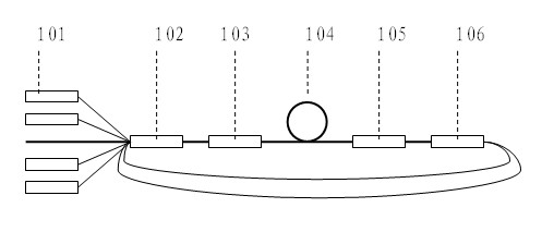
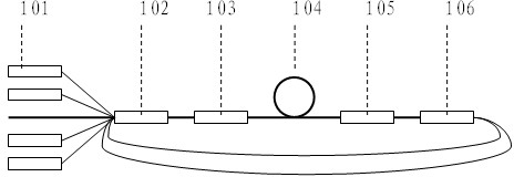
[0013] see first figure 1 , figure 1 It is a block diagram of the annular reverse pumping structure of the high-power all-fiber laser of the present invention. As can be seen from the figure, the annular reverse pumping structure of the high-power all-fiber laser of the present invention comprises a semiconductor laser pumping source 101 with a fiber pigtail, a beam combiner 102, a low-inverse fiber Bragg grating 103, and a gain fiber 104. , a high inverse Bragg grating 105 and a beam splitter 106, the beam combiner 102 is a (n+1)x1 beam combiner, including n pump light input fibers and 1 central main fiber, the split The beam splitter is a 1-m-way beam splitter, and the tail fibers of the n-m semiconductor lasers as the pumping source 101 are connected to the n-m input...


PUM


Abstract

The invention discloses an annular backward pumping structure of a high-power all-fiber laser. The annular backward pumping structure comprises a semiconductor laser pumping source with fiber pigtails, a beam combiner, a low-reflectivity fiber Bragg grating, a gain fiber, a high-reflectivity fiber Bragg grating and a beam splitter, wherein the beam combiner is an (n+1)x1 beam combiner and comprises n pumping light input fibers and a central main fiber; the beam splitter splits a beam into m paths; the fiber pigtails of (n-m) semiconductor lasers of the pumping source are connected with (n-m) input fibers of the beam combiner; an output end of the beam combiner is connected with an input end of the beam combiner through the low-reflectivity fiber Bragg grating, the gain fiber and the high-reflectivity fiber Bragg grating; and m output fibers of the beam combiner are connected with m input fibers of the beam combiner. By adoption of the annular backward pumping structure of the high-power all-fiber laser, the pumping light utilization rate of the conventional backward pumping structure of a high-power fiber laser can be effectively improved.

Description

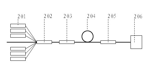
technical field [0001] The invention relates to an all-fiber laser, in particular to an annular reverse pumping structure of a high-power all-fiber laser. technical background [0002] The original high-power all-fiber laser reverse pumping structure such as figure 2 As shown, it consists of a semiconductor laser pump source 201 with a pigtail, a beam combiner 202, a low inverse Bragg fiber grating 203, a doped double-clad gain fiber 204, a high inverse fiber Bragg grating 205, and a light-absorbing heat sink 206. [0003] The laser light is output from the low inverse Bragg fiber grating, and its direction through the beam combiner is opposite to that of the pump light entering the beam combiner. The pump light passes through the low-inverse fiber Bragg grating, doped double-clad gain fiber, and high-inverse fiber Bragg grating in one pass, and the remaining pump light that is not absorbed is output through the high-inverse fiber Bragg grating, which is opposite to the out...

Claims


Application Information

Patent Timeline
Patent Type & Authority Applications(China)
IPC IPC(8): H01S3/0941H01S3/08H01S3/067
Inventor 何兵郑寄托周军范元媛代守军
Owner SHANGHAI INST OF OPTICS & FINE MECHANICS CHINESE ACAD OF SCI
Learn More