
Power transmission line pilot protection method based on magnitude of current

A transmission line and longitudinal protection technology, applied in emergency protection circuit devices, electrical components, etc., can solve the problems of neglecting distributed capacitance, high communication channel requirements, and increasing information transmission volume.

Inactive Publication Date: 2012-07-11
XI AN JIAOTONG UNIV
View PDF4 Cites 19 Cited by
  • Summary
  • Abstract
  • Description
  • Claims
  • Application Information

AI Technical Summary

Problems solved by technology

However, actual operating experience shows that this protection principle has the following defects: (1) This principle ignores the distributed capacitance existing in the actual transmission line
However, due to the use of double-ended voltage data, the voltage at one end is required to be transmitted to the opposite end, which increases the amount of information transmission and requires higher communication channels.

Method used


Image

  • Power transmission line pilot protection method based on magnitude of current
  • Power transmission line pilot protection method based on magnitude of current
  • Power transmission line pilot protection method based on magnitude of current

Examples


Embodiment Construction

[0117] The present invention will be described in more detail below in conjunction with the accompanying drawings and specific embodiments.

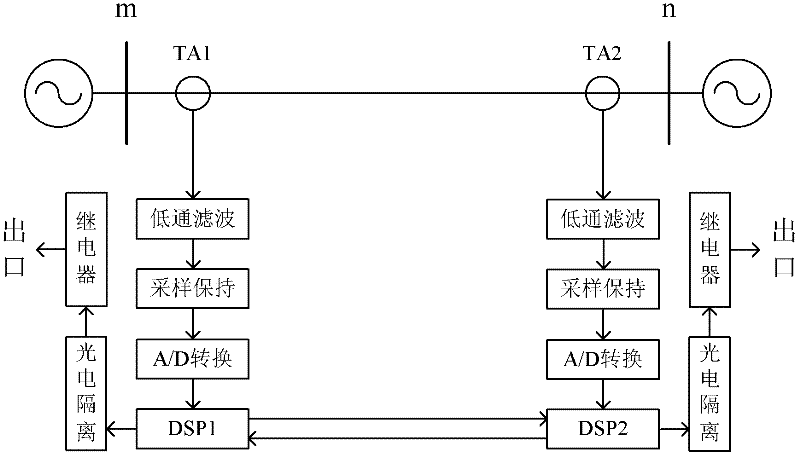
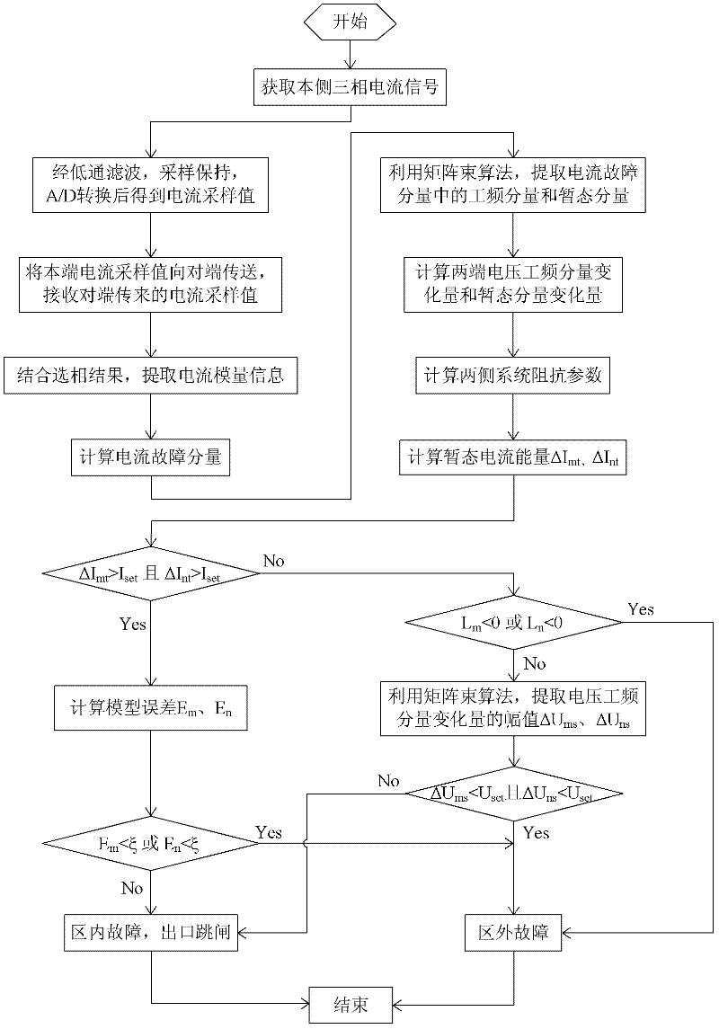
[0118] Such as figure 1 As shown, the present invention belongs to line microcomputer protection, and both sides of the line are equipped with protection devices using the principles of the present invention, and the protection devices on both sides exchange data through communication channels. figure 1 Depicts the connection relationship between hardware, figure 2The data processing flow is described. Taking the protection device on side m as an example, the current transformer TA1 on this side collects the analog quantity of the three-phase current on this side, and after low-pass filtering, sampling and holding, and A / D conversion, the digital quantity is obtained and input to DSP1, and DSP1 is equipped with The communication interface is also connected with the communication channel. On the one hand, the current digital quantity c...


PUM


Abstract

The invention relates to a power transmission line pilot protection method based on magnitude of current, which comprises the following steps: firstly, collecting A, B and C three-phase current of a current transformer by use of protective devices installed at two ends of a power transmission line, then treating the collected three-phase current to obtain sampling values; after that, sending the sampling values at the corresponding end of the power transmission line to the opposite end by each protective device which receives the sampling value sent from the opposite end; after that, performing phrase-to-modulus conversion on the sampling values of the three-phase current to obtain corresponding modulus information; computing current fault component at the two ends of the power transmission line as delta im(t) and delta in(t); after that, collecting power frequency component and transient component of the current fault component at the two ends of the power transmission line in sequence; computing power frequency component and transient component of voltage at installing parts of the protective devices at the two ends of the power transmission line; computing system impedance parameters at the two ends of the power transmission line as Lm, Rm and Ln, Rn; computing transient current energy; computing model error En and Em to judge the fault position if the transient current energy is relative big; and judging the fault position according to the changing amplitude of the system impedance parameters and the voltage and power frequency component. The power transmission line pilot protection method provided by the invention has the characteristics of only using information composition of two-end current and not being influenced by distributed capacitance.

Description

technical field [0001] The invention relates to the technical field of electric power system relay protection, in particular to a current-based longitudinal protection method for transmission lines. Background technique [0002] The longitudinal current differential protection has the advantages of simple criterion, high sensitivity, and natural phase selection ability, and is widely used as the main protection of transmission lines. However, actual operating experience shows that this protection principle has the following defects: (1) This principle ignores the distributed capacitance existing in the actual transmission line. With the increase of the voltage level of the transmission line and the increase of the line length, the distributed capacitance will become larger and larger, which makes the fault transient process more obvious, and the transient current will affect the calculation accuracy of the traditional protection algorithm; (2) Steady-state capacitance The c...

Claims


Application Information

Patent Timeline
Patent Type & Authority Applications(China)
IPC IPC(8): H02H7/26
Inventor 索南加乐马超康小宁
Owner XI AN JIAOTONG UNIV
Learn More