Apparatus, system, and method for reductant line heating control

A heating system and reducing agent technology, applied in chemical instruments and methods, separation methods, mechanical equipment, etc., can solve the problem that the temperature of the reducing agent cannot be kept higher than the freezing point of the reducing agent, etc.

Active Publication Date: 2012-07-11
CUMMINS INTPROP INC
View PDF5 Cites 11 Cited by
  • Summary
  • Abstract
  • Description
  • Claims
  • Application Information

AI Technical Summary

Problems solved by technology

[0011] In addition, another limitation of the conventional system is that the temperature of the reductant in the reductant line is kept above the freezing point of the reductant and below the temperature corresponding to the allowable temperature in the reductant delivery system due to the absence of a temperature sensor in the reductant line. Upper limit threshold for maximum temperature

Method used


Image

  • Apparatus, system, and method for reductant line heating control
  • Apparatus, system, and method for reductant line heating control
  • Apparatus, system, and method for reductant line heating control

Examples


Embodiment Construction

[0029] Reference in this specification to "one embodiment," "an embodiment," or similar language means that a particular feature, structure, or characteristic described in connection with the embodiment is included in at least one embodiment of the presently disclosed application. Appearances of the phrases "in one embodiment," "in an embodiment," or similar language in this specification may, but do not necessarily, all refer to the same embodiment. Similarly, use of the term "implementation" means an implementation having a particular feature, structure, or characteristic described in connection with one or more embodiments of the presently disclosed application, however, lacking an explicit relationship to otherwise specify that an implementation may be related to One or more embodiments are related.

[0030] In the following description, numerous specific details are provided to provide a thorough understanding of embodiments of the disclosed application. One skilled in t...


PUM


Abstract

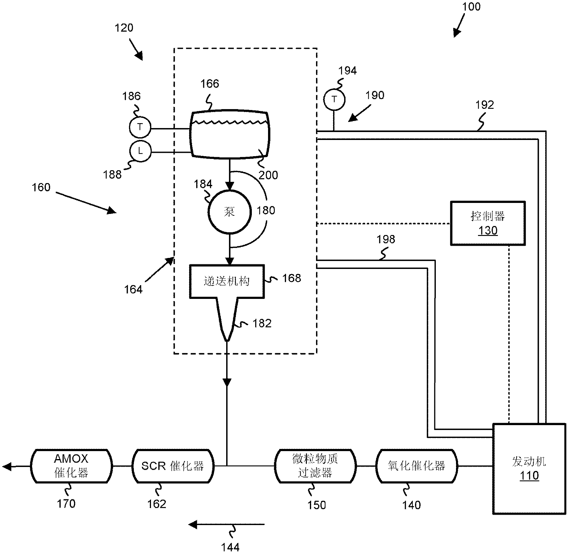
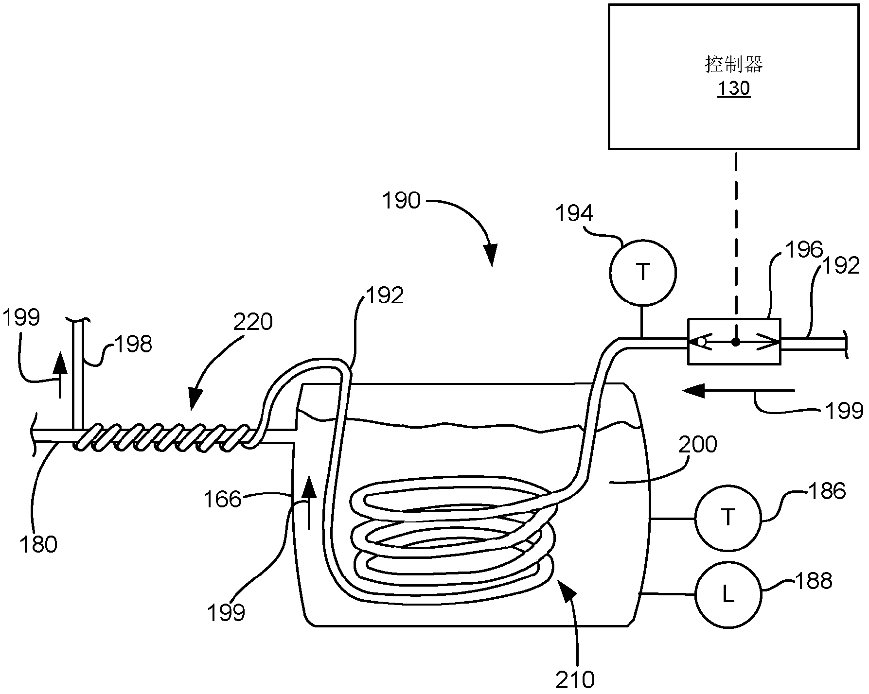
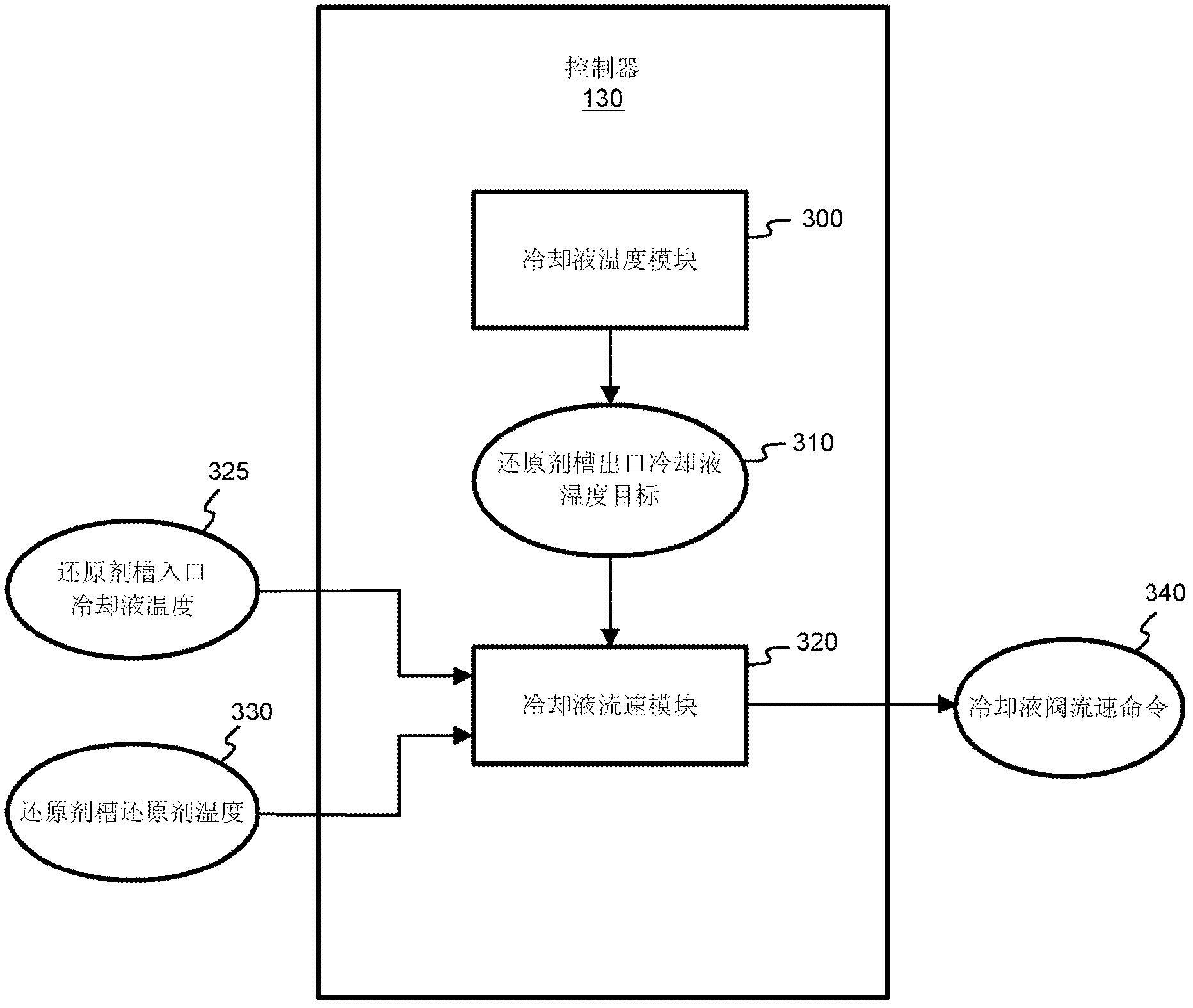
In one embodiment, an apparatus is disclosed for heating a reductant delivery line (180) using coolant from an internal combustion engine (110) where the reductant delivery line receives reductant (200) from a reductant tank (166) and a portion (210) of a coolant line (192) is positioned within the reductant tank. The apparatus includes a coolant temperature module (300) that is configured to determine a reductant tank outlet coolant temperature target (310). Additionally, the apparatus includes a coolant flow rate module (320) that is configured to generate a coolant valve flow rate command (340) and transmit the command to a coolant valve (196). The coolant valve is controllable to regulate the flow rate of coolant through the coolant line. The coolant valve flow rate command is based on the reductant tank outlet coolant temperature target, a reductant tank inlet coolant temperature (325), and a reductant tank reductant temperature (330).

Description

[0001] Cross References to Related Applications [0002] The claims of this application are the benefit of US Provisional Patent Application No. 61 / 218,222, filed June 18, 2009, which is incorporated herein by reference. field of invention [0003] The present invention relates to a selective catalytic reduction (SCR) system of an internal combustion engine, and more particularly, how to control the SCR system to reduce NO in exhaust gas x The temperature of the discharged reducing agent. Background technique [0004] Exhaust gas aftertreatment systems are used to receive and treat the exhaust gases produced by internal combustion engines. A typical exhaust aftertreatment system includes a number of components configured to reduce the level of harmful exhaust emissions present in the exhaust. For example, some exhaust aftertreatment systems for diesel internal combustion engines include multiple components such as a diesel oxidation catalyst (DOC), a particulate filter or ...

Claims


Application Information

Patent Timeline
Patent Type & Authority Applications(China)
IPC IPC(8): F01N3/28F01N3/20F01N9/00F01N3/10B01D53/94
CPCY02T10/24F01N3/208F01N2610/02F01N2610/105F01N2900/1811F01N2900/08F01N2900/0412F01N2610/1486F01N2610/10F01N2610/1406F01N2900/1814Y02A50/20Y02T10/12
Inventor 哈基姆·奥冈勒耶齐宝华米奇·麦克丹尼尔
Owner CUMMINS INTPROP INC
Why Eureka
Try Eureka