
Method for controlling direction of rotation axis and rotation direction of space universal superposition rotating magnetic field

A technology of rotating magnetic field and rotating direction, which is applied in the field of automation engineering technology, and can solve problems such as the inability to realize the control of the orientation and direction of the superimposed rotating magnetic field

Active Publication Date: 2012-07-18
DALIAN UNIV OF TECH
View PDF4 Cites 37 Cited by
  • Summary
  • Abstract
  • Description
  • Claims
  • Application Information

AI Technical Summary

Problems solved by technology

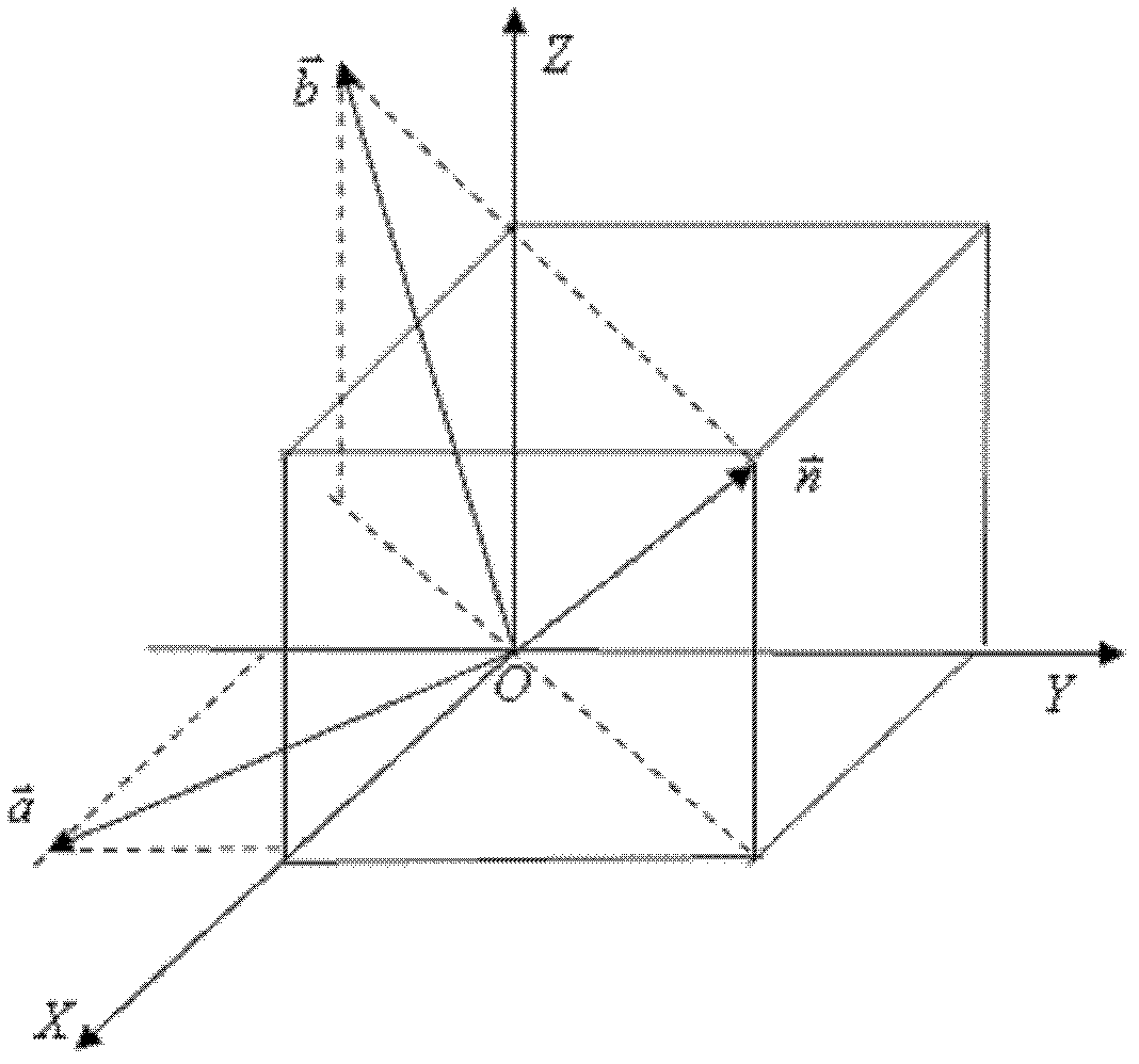
[0025] Equation (5) is the basic driving relational expression of the three-axis orthogonal Helmholtz coil superimposing the universal rotating magnetic field in space. Experiments have proved that the rotation axis of the superimposed rotating magnetic field in Equation (5) is only suitable for the first quadrant of the space coordinate system, and the magnetic field The direction of rotation is always clockwise, that is, when α, β, and γ are all acute angles, the superimposed rotation axis is the only one, which has limitations. According to this relationship, the control of the orientation and direction of the superimposed rotating magnetic field in other quadrants cannot be realized. Therefore, what is superimposed by formula (5) is not a true universal rotating magnetic field

Method used


Image

  • Method for controlling direction of rotation axis and rotation direction of space universal superposition rotating magnetic field
  • Method for controlling direction of rotation axis and rotation direction of space universal superposition rotating magnetic field
  • Method for controlling direction of rotation axis and rotation direction of space universal superposition rotating magnetic field

Examples


Embodiment

[0097] Implementation steps of the present invention are as follows:

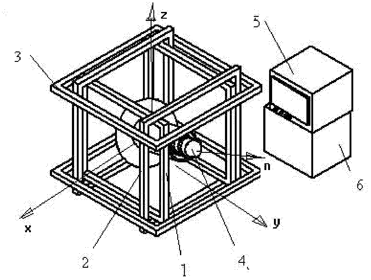
[0098] (1) Plan three-axis orthogonally nested Helmholtz coils to accommodate the micro-robot system: use the Helmholtz coil group 3 whose axis is the z-axis, and the Helmholtz coil group 2 whose axis is the y-axis and The installation plan of the Helmholtz coil group 2 whose axial direction is the x-axis is orthogonally nested in order from large to small. When designing the three groups of coils, the current matching problem must be considered, that is, when the same DC drive current is applied, the The DC magnetic field strength at the center of the three groups of coils should be equal. Since the large air gap of the coil size is also large, in order to increase the magnetic field strength at the center point under the same current, the number of coil turns must be increased to meet the current matching conditions. The numbers of turns of the sequential Helmholtz coil group 3 , Helmholtz coil group 2 an...


PUM


Abstract

The invention belongs to the technical field of automation engineering and discloses a method for controlling the direction of a rotation axis and the rotation direction of a space universal superposition rotating magnetic field. Three z-axis, y-axis and x-axis square Helmholtz coil groups are orthogonally nested, so that when the three groups of coils are driven by direct currents with the same current strength, the magnetic inductions generated at the center points of the three groups of coils have the same strength; the superposition rotating magnetic field is driven by an amplitude and phase compensation voltage signal through digitization so as to eliminate the influence of current lagging and inductive reactance on the current amplitude; and a same-frequency three-phase sinusoidal signal with the amplitude and the phase related to the axis azimuthal angle of a robot is used for driving to form the space universal uniform rotating magnetic field with the corresponding azimuthal rotating axis in a superimposed mode in a certain space surrounded by the three-axis orthogonal Helmholtz coil devices. According to the invention, by implementing the random regulation of the direction of the rotation axis and the rotation direction of the space universal rotating magnetic field, various operations of turning, moving forward, moving backward and the like of the micro robot in the bent or branch cavity environment are further implemented; and the method has wide application prospect.

Description

technical field [0001] The invention belongs to the technical field of automation engineering, and relates to a technical approach of applying anti-phase current to the same-frequency three-phase sinusoidal current signal with the relative amplitude and phase of a certain fixed axis azimuth angle in space as the input variable to realize three-axis orthogonal A unique control method for the rotation axis orientation and rotation direction (clockwise or counterclockwise) of the superimposed spatially uniform rotating magnetic field in a certain space within the nested Helmholtz coil device. Background technique [0002] Capsule robots are expected to complete tasks such as diagnosis, sampling and spraying in the human body, and have important application value in the field of medical engineering. People have developed capsule endoscopes that rely on gastrointestinal peristalsis and put them into clinical applications, but they have not yet achieved posture Active control cann...

Claims


Application Information

Patent Timeline
IPC IPC(8): A61B5/07A61B1/00
Inventor 张永顺王殿龙谢华英岳明杨振强
Owner DALIAN UNIV OF TECH
Learn More