
Minimally-invasive endoscopic visual uterine cavity tissue suction tube

A technology for visualizing the uterine cavity and suction tube, which is applied in the field of medical equipment, can solve the problems of camera swimming, affecting the camera effect, and the breakage of the suction head, so as to prevent medical accidents, improve the effect of surgery, and ensure the effect of camera

Inactive Publication Date: 2012-07-18
SHANGHAI YODO MEDICAL TECH
View PDF14 Cites 8 Cited by
  • Summary
  • Abstract
  • Description
  • Claims
  • Application Information

AI Technical Summary

Problems solved by technology

[0006] However, the visible intrauterine suction tube in the prior art including the above two patent solutions (disposable visible intrauterine suction tube) has the following shortcomings : First, because the setting of the camera in the camera cabin is unreasonable, the lens of the camera is directed away from the direction of the suction hole of the suction head of the suction tube body, so the angle of view is quite different from the direction of the suction hole. And the field of view is significantly smaller than the range of the suction hole, which leads to a blind spot in the camera. During the operation, the doctor can only vaguely see or even see part of the embryo sac, which is not enough to guarantee the effect of the operation (the concept of viewing angle can be obtained through China The patent ZL20092009442.2 has been fully understood; the field of view refers to the angle between the two edges of the maximum range of the object image of the measured target passing through the lens of the camera); the second is that the suction head with the suction hole and the suction tube body After being made separately, the two are glued together as a whole. Therefore, once the force is too large during use, the fragile suction head will break and fall off in the uterine cavity, causing unwanted medical accidents; the third is Because the hatch cover of the camera compartment installed with the camera cannot be positioned for the camera, there is a swimming phenomenon in the camera during use, which affects the camera effect; the fourth is due to the lack of shielding measures for the suction head in the non-activated state, so in the In the process of product packaging and storage, there is not only the risk of damage to the suction head and camera compartment, but also the risk of external dust intruding into the suction hole

Method used


Image

  • Minimally-invasive endoscopic visual uterine cavity tissue suction tube
  • Minimally-invasive endoscopic visual uterine cavity tissue suction tube
  • Minimally-invasive endoscopic visual uterine cavity tissue suction tube

Examples


Embodiment Construction

[0026] In order to enable the examiners of the patent office, especially the public, to understand the technical essence and beneficial effects of the present invention more clearly, the applicant will describe in detail the following in the form of examples, but none of the descriptions to the examples is an explanation of the solutions of the present invention. Any equivalent transformation made according to the concept of the present invention which is merely formal but not substantive shall be regarded as the scope of the technical solution of the present invention.

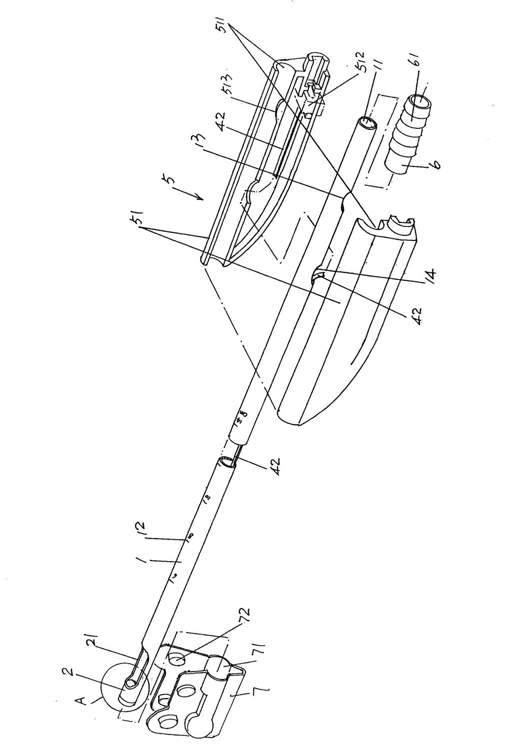
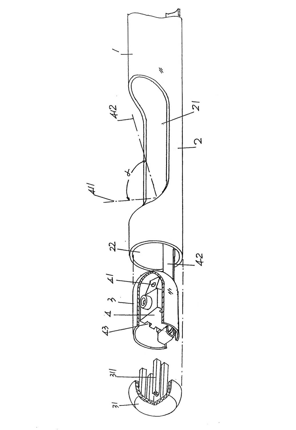
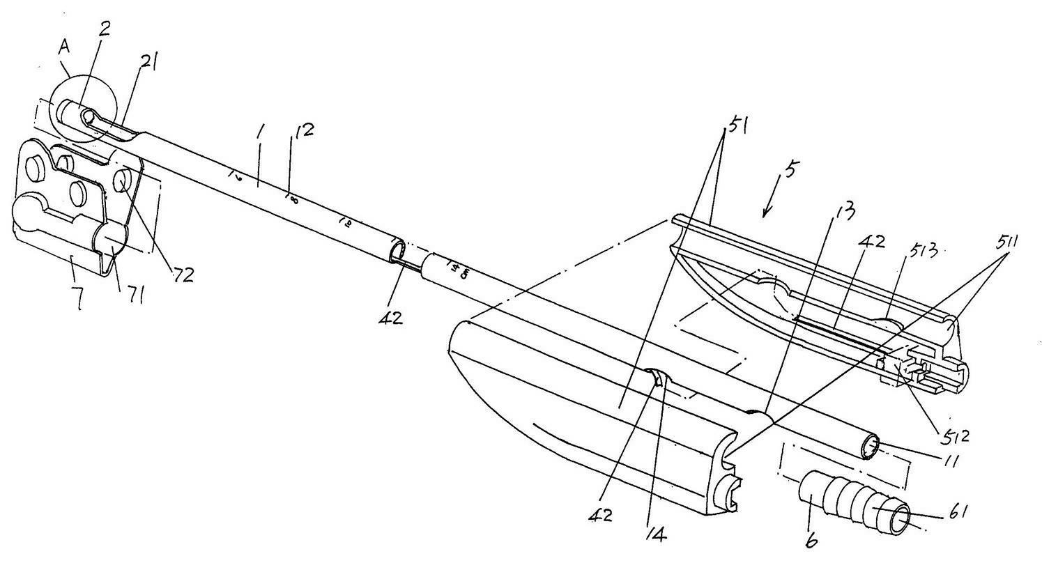
[0027] Please see figure 1 and figure 2 , the suction tube body 1 is preferably made of non-toxic medical grade and transparent polyvinyl chloride, and a lumen 11 is formed in the length direction of the suction tube body 1 . at present figure 1 The position state shown is an example, a suction head 2 with a suction hole 21 is combined at the left end of the suction tube body 1. In this embodiment,...


PUM


Abstract

A minimally-invasive endoscopic visual uterine cavity tissue suction tube belongs to the medical apparatus technical field. The minimally-invasive endoscopic visual uterine cavity tissue suction tube comprises a suction tube body, a suction head, a pick-up head cabin, a pick-up head, a handle, and a joint, and is characterized in that a lens of the pick-up head faces a suction hole of the suction head; the suction head and the suction tube body form an integral structure; corresponding two side outer walls of the pick-up head are provided with pick-up head limiting grooves, respectively; one side of a cabin cover facing the pick-up head cabin , corresponding to the pick-up head limiting grooves, is provided with limiting strips and the limiting strips are matched with the limiting grooves of the pick-up head. The minimally-invasive endoscopic visual uterine cavity tissue suction tube provided by the invention has the advantages of being capable of avoiding blindness, facilitating clear observation of overall embryo sac by doctors, improving surgery effect, avoiding the forced breakage of the suction head and falling off in the uterine cavity during a surgery process, eliminating surgical accidents, and reliably positioning the pick-up head to guarantee the shooting effect of the uterine cavity.

Description

technical field [0001] The invention belongs to the technical field of medical devices, in particular to a minimally invasive endoscopic visible uterine cavity tissue suction tube. Background technique [0002] Uterine cavity tissue suction tube is usually referred to as a one-time-use artificial abortion suction tube in clinical practice. There is no lack of technical information about uterine cavity tissue suction tube in the published Chinese patent documents. For example, the authorized announcement CN2675062Y (abortion suction tube), CN2488478Y (electric abortion suction tube) and CN200954128Y (abortion suction tube), and CN201361807Y (disposable abortion suction tube), which overcomes the deficiencies of these three patents, etc. [0003] The disadvantages of the uterine cavity tissue suction tube disclosed in the above-mentioned patents are: since the specific situation in the uterus cannot be observed during the operation, the process of suctioning the uterine cavit...

Claims


Application Information

Patent Timeline
IPC IPC(8): A61B17/42A61M1/00A61M1/04
Inventor 郝进争
Owner SHANGHAI YODO MEDICAL TECH
Learn More