
Method for manufacturing anode screen plate for improving solar cell silicon sheet conversion rate

A technology of silicon cell and manufacturing method, applied in printing, printing plate preparation and other directions, can solve the problems of unevenness, the conversion efficiency of solar silicon cell cannot be broken through, and the printing disconnection, etc., to achieve uniform printing, reduced area, The effect of improved conversion efficiency

Active Publication Date: 2012-07-18
SUZHOU OUFANG ELECTRONICS TECH
View PDF7 Cites 24 Cited by
  • Summary
  • Abstract
  • Description
  • Claims
  • Application Information

AI Technical Summary

Benefits of technology

This patented technology improves the quality of photovoltaic cells by optimizing their design for better performance compared to traditional methods like adding extra components or adjusting certain parameters such as light intensity levels.

Problems solved by technology

This patented technical problem addressed by this patents relates to improving the performance of solar cell devices made from crystalline silicon wafers for use on both terrestrial (Solar) power generation systems and space applications where high temperatures are present during operation. Specifically, there may occur issues when small particles called tiny cracks form along certain areas within these panels which can cause electrical shorts between different parts of the device's circuitry. These minute defects could affect its overall effectiveness and even result into failure if they were left unnoticeable after manufacturing.

Method used


Image

  • Method for manufacturing anode screen plate for improving solar cell silicon sheet conversion rate
  • Method for manufacturing anode screen plate for improving solar cell silicon sheet conversion rate
  • Method for manufacturing anode screen plate for improving solar cell silicon sheet conversion rate

Examples


Embodiment Construction

[0019] The present invention will be further described below in conjunction with the accompanying drawings.

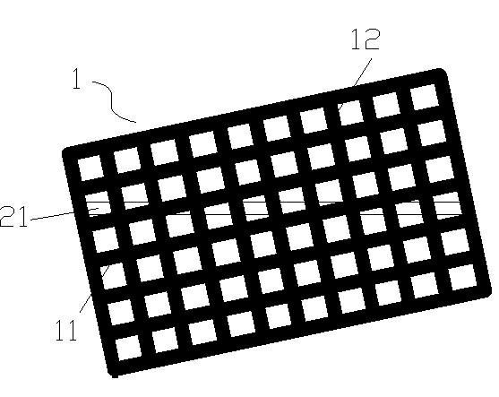
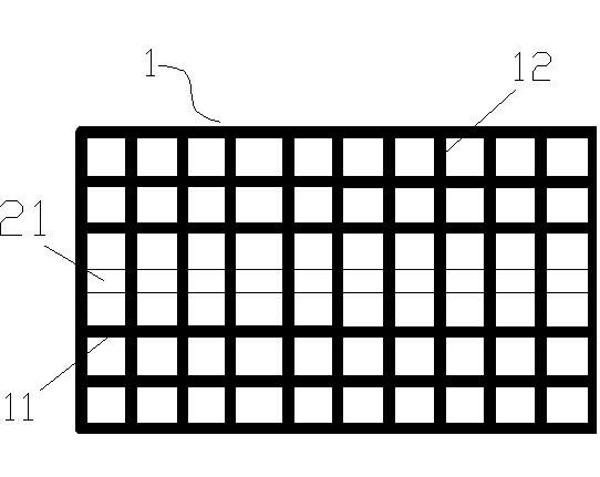
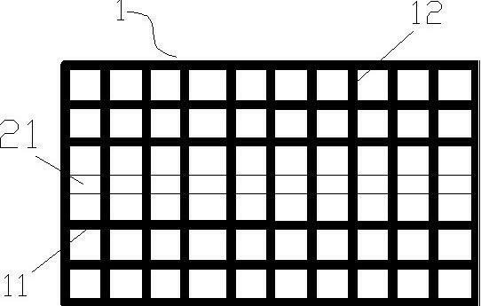
[0020] A method for manufacturing a positive electrode screen plate with a high conversion rate of solar silicon cells, comprising the steps of:

[0021] (1) Input the printed graphics of the positive electrode of the solar silicon cell and the standard screen panel graphics provided by the customer into the corresponding computer software, such as AutoCAD and other drawing software for superimposed comparison;

[0022] (2) According to the analysis of the computer software, adjust the spacing of the adjacent meridians at the fine grid line of the positive electrode printing pattern of the screen plate corresponding to the solar silicon cell to increase it to 2-3 times the original spacing;

[0023] (3) Adjust the diameter of the warp and weft of the positive electrode screen plate outside the positive electrode printing pattern of solar silicon cells to 1.5-2 times of...


PUM

PropertyMeasurementUnit
Wire diameteraaaaaaaaaa

Abstract

The invention provides a method for manufacturing an anode screen plate for improving the solar cell silicon sheet conversion rate. The method comprises the following steps: 1, superposing and contrasting an anode printing figure and a screen plate figure by computer software; 2, adjusting the spacing between adjacent longitude wires on the fine grid wire part of the anode printing figure of a corresponding solar cell silicon sheet; 3, increasing the wire diameters of the longitude wires and latitude wires of the anode screen plate outside of the anode printing figure of the solar cell silicon sheet; and 4, completing the manufacturing of the screen plate through in an electroforming or micro-cutting manner according to the figure. The method solves a problem that the conversion rate of the solar cell silicon sheet cannot breakthrough because the printing of screen plates in the prior art is discontinuous and nonuniform, and the spacing between the adjacent longitude wires of the screen plate is adjusted to make the fine grid wire of the anode printing figure have no network nod blocks. The screen plate manufactured through adopting the method has the advantages of no discontinuity after the silver slurry printing, uniform printing, fine grid wire width, and improvement of the cell sheet conversion rate.

Description


Claims


Application Information

Patent Timeline
Owner SUZHOU OUFANG ELECTRONICS TECH
Learn More