Sludge storage bin system

A sludge and silo technology, which is applied in containers, packaging, transportation and packaging, etc., can solve the problems of affecting the transmission efficiency, the conveying mechanism is not finished conveying, and the warehouse is full, so as to achieve smooth operation of the carriage, uniform force, and prevent transmission. The effect of efficiency

Inactive Publication Date: 2014-01-22
CHINA JILIANG UNIV
View PDF7 Cites 0 Cited by
  • Summary
  • Abstract
  • Description
  • Claims
  • Application Information

AI Technical Summary

Problems solved by technology

However, there is a certain delay in using the pressure sensor to judge whether there is a certain delay, that is, the lower end of the silo has stopped dropping materials, but there is still a part of the conveying mechanism that has not been conveyed, which affects the judgment. Therefore, there is a certain time difference.
[0003] In addition, the prior art also has the following deficiencies: 1. Since the speed of the material conveying mechanism in the prior art is constant, when there are too many materials in the silo, the phenomenon that the silo may be full due to the inability to adjust the speed; When there are few materials in the silo, the materials in the silo tend to be insufficient or even empty
2. The composition of sludge is relatively complex, and it is easy to produce harmful gases such as methane and hydrogen sulfide, and has a certain odor
3. The feed bin is fed on the screw conveyor, and the screw conveyor squeezes the material to the conveying mechanism. The existing technology uses a single screw conveyor. Due to the high viscosity of the sludge, the single screw conveyor squeezes the sludge material. During the pressing process, sludge will stick to itself, which will affect the transmission efficiency

Method used


Image

  • Sludge storage bin system
  • Sludge storage bin system

Examples


Embodiment Construction

[0016] The present invention will be further described below in conjunction with the accompanying drawings and specific embodiments.

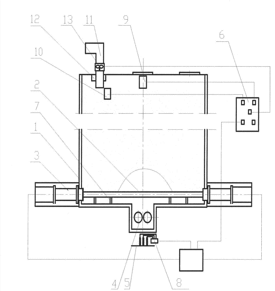
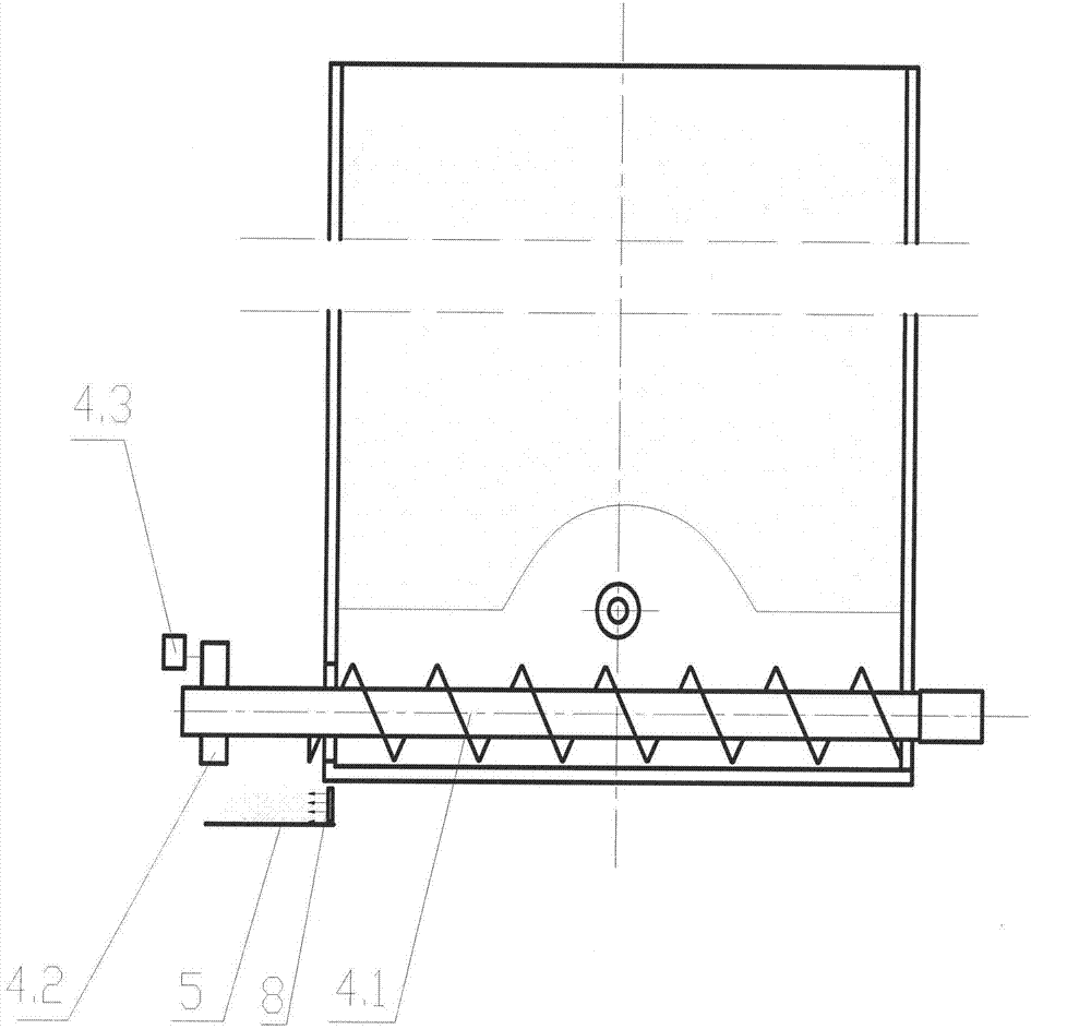
[0017] Such as figure 1 , 2 As shown, the sludge silo system of the present invention includes a silo body 1, a carriage 2, a hydraulic cylinder 3, a screw conveyor 4, a sludge transmission mechanism 5 and a controller 6, and the carriage 2 is arranged on the material At the bottom of the bin body 1, there are two hydraulic cylinders 3, which are respectively installed on both sides of the carriage 2, and the piston end of the hydraulic cylinder 3 is connected with the carriage 2; the carriage 2 is connected to the inner bottom surface of the bin body 1 There are guide rails 7 between them, the screw conveyor 4 is installed under the slide frame 2, the sludge transfer mechanism 5 is arranged under the outlet of the screw conveyor 4, and an infrared conveyor is installed on the sludge transfer mechanism 5. The sensor 8, the infrared sensor 8 a...


PUM


Abstract

The invention discloses a sludge storage bin system, which comprises a storage bin body (1), a sliding rack (2), two hydraulic cylinders (3), a screw conveyer (4), a sludge conveying mechanism (5) and a controller (6). The sliding rack (2) is arranged at the bottom of the storage bin body (1), piston ends of the hydraulic cylinders are connected with the sliding rack (2), a guide rail (7) is arranged between the sliding rack and the inner bottom of the storage bin body, the screw conveyer is mounted below the sliding rack, the sludge conveying mechanism is arranged below an outlet of the screw conveyer (4), an infrared sensor (8) is arranged on the sludge conveying mechanism (5), the infrared sensor (8) and the hydraulic cylinders (3) are electrically connected with the controller (6), and the screw conveyer (4) is a two-screw conveyer comprising two screw conveying rods (4.1) and a driving motor (4.2). The sludge storage bin system has the advantages that whether a storage bin bulges or not can be detected in real time, conveying speed can be adjusted, environmental protection is realized, and conveying efficiency is high.

Description

technical field [0001] The invention relates to the field of sludge treatment equipment, in particular to a sludge silo system comprising a silo body and a sludge quantitative conveying device. Background technique [0002] In modern industry, the number and capacity of silos are increasing, and the frequency of use is also increasing. Relying on the bulk material to flow into the silo by its own gravity, material arching, sticking, clogging and other phenomena are prone to occur, especially when the material contains a large amount of water and mud. Once the silo is blocked, it will not only affect the full play of the silo, but also seriously affect the continuity of the production process. Therefore, how to remove situations such as silo arching, bonding, and blockage in the safest, most energy-saving, and fastest method has become an urgent problem to be solved. At present, the methods of clearing and breaking arches include artificial arch breaking method, water conse...

Claims


Application Information

Patent Timeline
Patent Type & Authority Patents(China)
IPC IPC(8): B65D88/68
Inventor 饶宾期曹黎赵明岩施阁
Owner CHINA JILIANG UNIV
Why Eureka
Try Eureka