
Printing and dyeing dropping machine

A technology of dripping machine and mother liquor, which is applied in textile processing machine accessories, dyeing devices for processing textile materials, textiles and papermaking, etc. It can solve problems such as low efficiency, inclination or inaccurate positioning of syringes, and affecting the normal operation of the liquid extraction process, etc. , to achieve the effect of precise positioning

Active Publication Date: 2013-11-13
厦门瑞比精密机械有限公司
View PDF2 Cites 9 Cited by
  • Summary
  • Abstract
  • Description
  • Claims
  • Application Information

AI Technical Summary

Problems solved by technology

However, because the mouth of the mother solution bottle made of glass is formed irregularly, the bottle mouth is randomly deformed. If the bottle mouth is used to position the syringe, the syringe will be tilted or the positioning position will be inaccurate, and its adjacent mother solution will be involved. bottle, thereby affecting the normal operation of the liquid extraction process;
[0005] 2. The liquid dispensing area of ​​the machine includes a straight conveyor belt. There are one or two rows of dyeing cups on the conveyor belt. The masterbatch in the mother liquid bottle is transferred to the dyeing cups through the syringe, and then diluted with water by the liquid dispensing device to achieve the dye ratio. Requirements, however, the efficiency of the liquid dosing method of the straight conveyor belt structure is low, the machine and the conveyor belt extend to the outside, occupy a large space in the laboratory or workshop, and the cost is high. In addition, the dyeing cup on the conveyor belt is often positioned at the dilution position The problem of deviation

Method used


Image

  • Printing and dyeing dropping machine
  • Printing and dyeing dropping machine
  • Printing and dyeing dropping machine

Examples


Embodiment

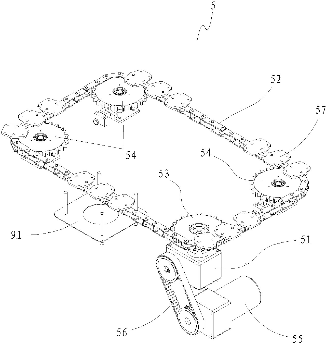
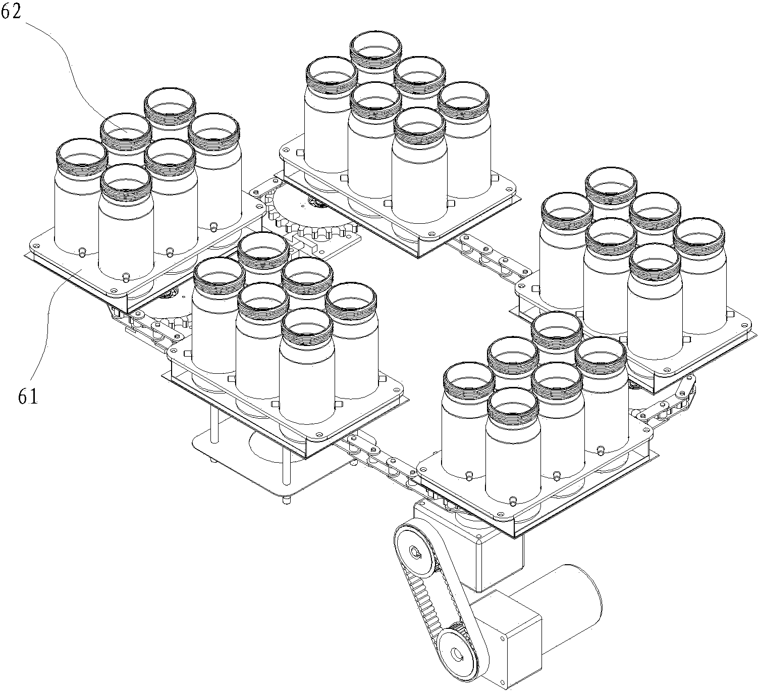
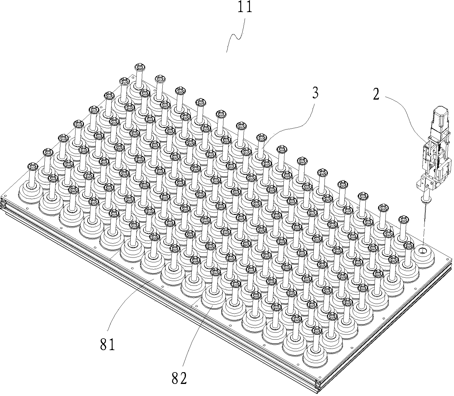
[0030] Example: see Figure 1 to Figure 5 , a printing and dyeing machine, comprising:

[0031] Machine 1, which has a liquid taking area 10 for accommodating multiple mother liquid bottles and a liquid dispensing area 11 located on one side thereof, a three-axis manipulator 2 is arranged above the liquid taking area, and the manipulator cooperates with a syringe 3 to transfer the mother liquid to the dosing area and insert the syringe back into the corresponding mother solution bottle 4;

[0032] The liquid taking area 10 is provided with a positioning mechanism, and the positioning mechanism has a plurality of positioning holes, and a mother liquid bottle 4 is placed in each positioning hole, and each mother liquid bottle is equipped with a syringe 3, and the three-axis manipulator 2 holds one of the syringes Or play it back to the corresponding mother solution bottle based on the positioning hole where the mother solution bottle is located;

[0033] The liquid dispensing ...


PUM


Abstract

The invention discloses a printing and dyeing dropping machine, which comprises a bench provided with a liquid extracting area and a liquid distributing area, wherein the liquid extracting area contains a plurality of mother liquid bottles, and the liquid distributing area is positioned on one side of the liquid extracting area. A three-axis manipulator is arranged above the liquid extracting area, a positioning mechanism is arranged on the liquid extracting area, and a turntable mechanism is arranged on the liquid distributing area and is connected with a divider to precisely control a steel cup on the turntable mechanism to be matched with an outlet of a liquid distributing mechanism in a positioned manner. An injector can be precisely positioned by a positioning sleeve and an acrylic positioning plate, perpendicularity of the injector can be kept, and the problem of positioning in dye dropping is solved. When liquid is distributed, a turntable-type circulating structure is used for weighing and liquid distributing operations. When a motor stops rotating, the cup can be precisely transferred to a next cup position by the aid of the limit function of the divider, and positioning deviation of the cup and the liquid distributing mechanism due to movement inertia is avoided.

Description

technical field [0001] The invention discloses a printing and dyeing liquid dripping machine, which belongs to the technical field of printing and dyeing laboratory machinery manufacturing according to the International Patent Classification (IPC), and in particular relates to an automatic printing and dyeing proofing liquid dripping machine system for the printing and dyeing industry in the textile field. Background technique [0002] The traditional dye automatic drip metering device is mainly divided into two types: pipeline type and non-pipeline type dripping liquid. One of the non-pipeline dye automatic drop liquid metering devices is designed by using a turntable pipeline instead of The dripping conduit is provided with a raw material container (mother liquid bottle) turntable on a frame, and a plurality of raw material containers (mother liquid bottle) are arranged in a ring shape on it. A dyeing cup turntable is arranged below the raw material container turntable. T...

Claims


Application Information

Patent Timeline
Patent Type & Authority Patents(China)
IPC IPC(8): D06B23/00
CPCD06B23/10D06B23/205
Inventor 汤瑞能
Owner 厦门瑞比精密机械有限公司
Learn More