Exhaust system for steam turbine
A technology for steam turbines and exhaust devices, applied in mechanical equipment, engine components, engine manufacturing, etc., can solve the problems of blocked flow channels, short axial distances, and performance degradation, reducing pressure loss, providing efficiency, inhibiting chaotic effect
- Summary
- Abstract
- Description
- Claims
- Application Information
AI Technical Summary
Problems solved by technology
Method used
Image
Examples
no. 1 approach
[0043] (structure)
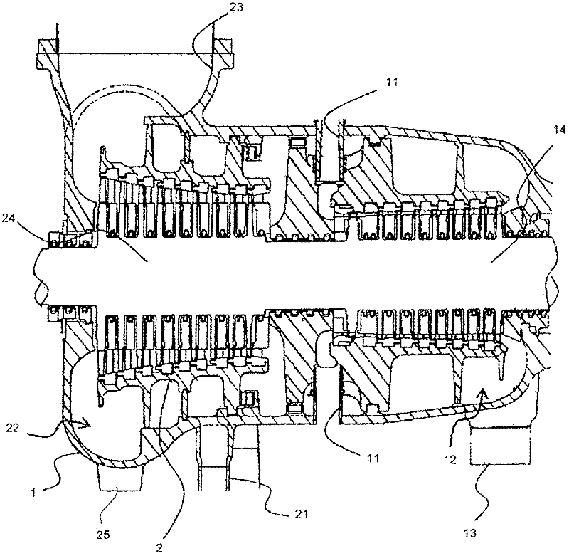
[0044] figure 1 It is a sectional view showing a schematic structure of a high and medium pressure section of a steam turbine to which the present invention is applied. The steam that has flowed in from the high-pressure inlet portion 11 flows out to the high-pressure exhaust pipe 13 through the high-pressure exhaust chamber 12 after being operated in the high-pressure turbine section 14 . The steam flowing out of the high-pressure exhaust chamber 12 through the high-pressure exhaust pipe 13 flows into the intermediate-pressure turbine section 24 from the reheat inlet pipe 21 through the boiler (not shown), and passes through the intermediate-pressure exhaust chamber after the operation of the intermediate-pressure turbine section 24 22 flows out to the medium pressure exhaust pipe 23. On the other hand, the steam extracted through the extraction pipe 25 is guided to the heater to be heated.
[0045] The exhaust device includes an inner casing 2 coverin...
no. 2 approach
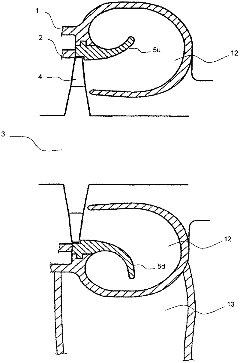
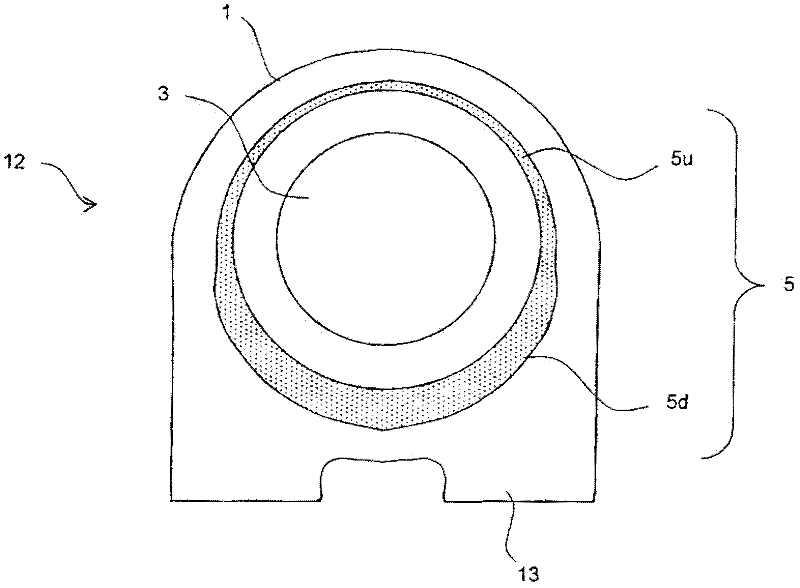
[0078] In the first embodiment, the vicinity of 100° to 180° is defined as the deflector downstream portion 5d, and the deflector occupancy ratio of the deflector downstream portion 5d is set to 0.7; The vicinity of 100° to 150° of the joint portion of the slit is defined as the most downstream portion 5d1 of the flow guide, and the flow guide occupancy ratio of the most downstream portion 5d1 of the flow guide is set to 0.7.
[0079] Figure 10 It is a figure which shows an example of the shape of the flow guide 5B. Set the flow guide occupancy ratio of the flow guide upstream part 5u (0-80°) to 0.4, set the flow guide occupancy ratio of the flow guide most downstream part 5d1 (100-150°) to 0.7, and set The flow guide occupancy ratio of the flow guide downstream part 5d2 (170-180°) is set to 0.4, and the flow guide occupancy ratios (80-100° and 150-170°) are continuous between 0.4-0.7. As a result, the cross-sectional view of the air guide 5B is as follows Figure 11 shown...
no. 3 approach
[0082] In the first embodiment and the second embodiment, the invention of the present application was applied to the exhaust chamber 12 provided with two exhaust pipes 13 on the downstream side, but it may also be applied to an exhaust chamber 12 provided with one exhaust pipe 13. Air chamber 12.
[0083] Figure 12 It is a figure which shows an example of the shape of 5 C of flow guides. The flow guide occupancy ratio of the flow guide upstream part 5u (0-120°) is set to 0.4, and the flow guide occupancy ratio of the flow guide downstream part 5d (160-180°) is set to 0.7, during which ( 120° to 160°), the occupation ratio of the guide element is continuous between 0.4 and 0.7. As a result, the cross-sectional view of the flow guide 5C is as follows Figure 13 shown.
[0084] The same effect as that of the first embodiment can also be obtained in the third embodiment.
PUM
 Abstract
Description
Claims
Application Information
 - R&D
- Intellectual Property
- Life Sciences
- Materials
- Tech Scout
- Unparalleled Data Quality
- Higher Quality Content
- 60% Fewer Hallucinations
Browse by: Latest US Patents, China's latest patents, Technical Efficacy Thesaurus, Application Domain, Technology Topic, Popular Technical Reports.
© 2025 PatSnap. All rights reserved.Legal|Privacy policy|Modern Slavery Act Transparency Statement|Sitemap|About US| Contact US: help@patsnap.com


