
Efficient flow-guide electric-control silicone oil fan clutch assembly

A clutch and fan technology, applied in the direction of fluid clutch, clutch, coolant flow control, etc., can solve the problems that affect the best working state of the engine, the slow flow speed of electronically controlled silicon oil circulation, and the prolongation of disengagement response time, etc.

Inactive Publication Date: 2012-07-18
温州车舟汽车部件有限公司
View PDF5 Cites 13 Cited by
  • Summary
  • Abstract
  • Description
  • Claims
  • Application Information

AI Technical Summary

Problems solved by technology

The magnetic guide sheet (also known as the valve sheet) of the existing electronically controlled silicon oil fan clutch assembly is installed on the front cover, which belongs to a part of the driven assembly, and forms electromagnetic induction with the solenoid valve assembly, and the centrifugal force it receives is compared with the oil return force. Small, the circulation speed of electronically controlled silicon oil is relatively slow, and the response time for the engagement and disengagement of the active part and the driven part of the fan clutch assembly will be prolonged accordingly, thus affecting the best working state of the engine to a certain extent

Method used


Image

  • Efficient flow-guide electric-control silicone oil fan clutch assembly
  • Efficient flow-guide electric-control silicone oil fan clutch assembly
  • Efficient flow-guide electric-control silicone oil fan clutch assembly

Examples


Embodiment Construction

[0010] The present invention will be described in further detail below in conjunction with the accompanying drawings and embodiments.

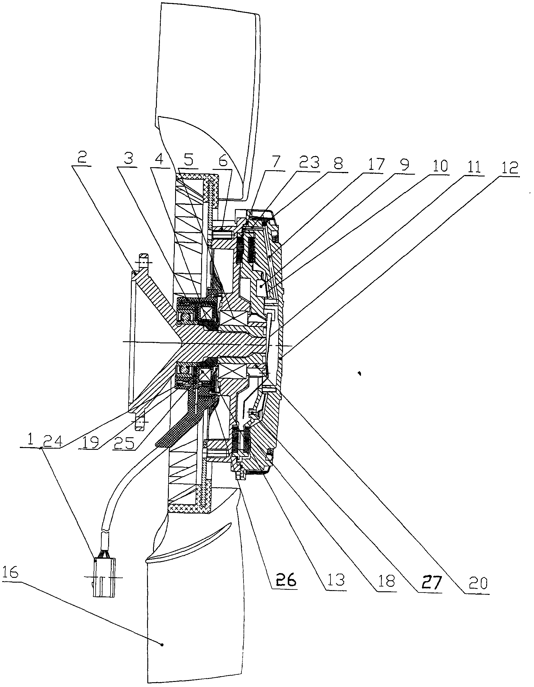
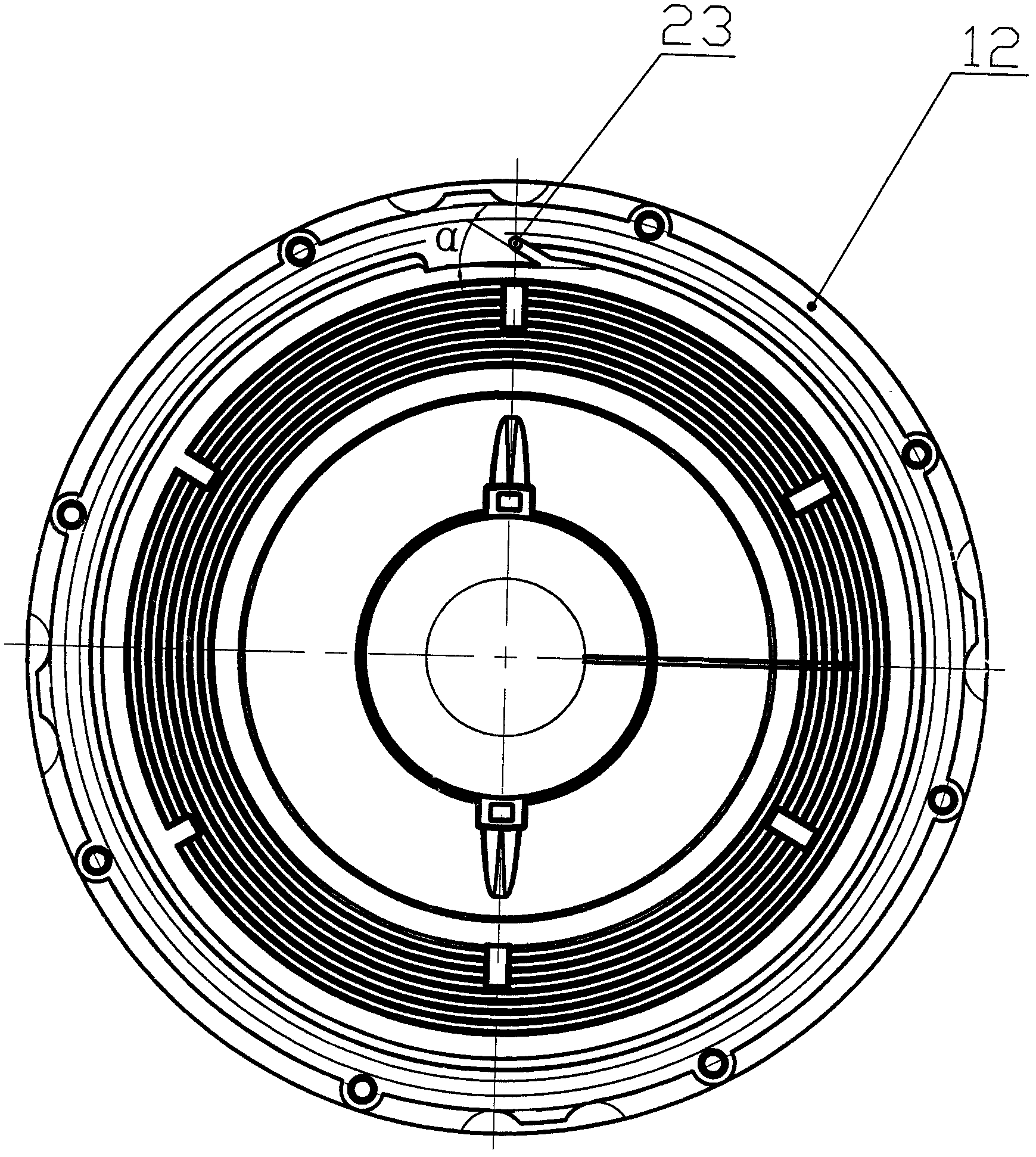
[0011] refer to figure 1 , figure 2 As shown, the present invention is applied to the high-efficiency guide type electronically controlled silicon oil fan clutch assembly of the automobile engine cooling system, including the driving shaft 2, the housing 6, the driving plate 7, the driven plate 10, and the front cover 12. 6 is equipped with a fan 16, on the drive shaft 2 (and close to its bearing 5) is equipped with a solenoid valve assembly 3, on the drive plate 7, and close to the drive shaft 2 is equipped with a magnetic guide sheet 11 (also known as valve plate), an oil storage cavity 9 is provided on the active plate 7 and between the driven plate 10, and an oil storage chamber 9 is provided in the front cover 12 (through the oil return hole 23 thereon). A circulating oil passage 17 communicated with the cavity 9, a working chamber 18 ...


PUM


Abstract

The invention discloses an efficient flow-guide electric-control silicone oil fan clutch assembly. The clutch assembly comprises a driving shaft (2), a shell (6), a driving plate (7), a driven plate (10) and a front cover (12), wherein a fan (16) is arranged on the shell, a solenoid valve component (3) is arranged on the driving shaft, a magnetic conducting piece (11) is arranged on the driving plate and close to the driving shaft, an oil storage chamber (9) is arranged on the driving plate and between the driving plate and the driven plate, a circulating oil way (17) communicated with the oil storage chamber (9) is arranged in the front cover, and a working cavity (18) communicated with the oil storage chamber and the circulating oil way is arranged between the shell and the driving plate as well as the front cover and the driving plate. With the fan clutch assembly, the circulating and flowing speed of the silicone oil can be raised, the meshing response time and the separating response time between the driving part and the driven part of the fan clutch assembly are relatively shortened, and the rotating speed of the fan is controlled in real time, so that an engine runs at an optimal temperature all the time, and the purposes of energy saving, emission reduction and noise reduction of an automobile are realized.

Description

technical field [0001] The invention relates to an engine cooling system, in particular to a silicone oil fan clutch assembly applied to an automobile engine cooling system. Background technique [0002] At present, the silicone oil fan clutch assembly is an important part of the engine cooling system on the car, which plays a key role in the energy saving, emission reduction, noise reduction and prolonging the service life of the car. The electronically controlled silicone oil fan clutch assembly replaces the original temperature-sensitive silicone oil fan clutch assembly, which controls the engagement and disengagement response time of the active part and the driven part of the fan clutch assembly through the circulating flow speed of the electronically controlled silicone oil, and The sensor board and the hall sensor in the solenoid valve assembly are used to feed back the fan speed signal in real time to achieve accurate closed-loop control, so that the engine can run at...

Claims


Application Information

Patent Timeline
IPC IPC(8): F01P7/04F16D35/00
Inventor 叶舟张春铎
Owner 温州车舟汽车部件有限公司
Learn More