High-speed punching hydraulic circuit of hydraulic punching machine

A stamping machine tool and high-pressure circuit technology, which is applied to mechanical equipment, fluid pressure actuation devices, fluid pressure actuation system components, etc., can solve the problems of power consumption, high heat generation noise, large heat generation, and short service life of hydraulic pumps. To achieve the effect of reducing power consumption

Inactive Publication Date: 2012-07-18
SHANDONG FIN CNC MACHINE
View PDF6 Cites 6 Cited by
  • Summary
  • Abstract
  • Description
  • Claims
  • Application Information

AI Technical Summary

Problems solved by technology

The stamping speed of the pure high-pressure circuit is fast, but the power consumption is high, the heat generation is large, and the high-pressure operation will have a great impact on the pipeline and sealing, the failure rate is relatively high, and the service life of the hydraulic pump is short
The circuit with low pressure with accumulator and high pressure without accumulator is very fast when the oil cylinder is empty, but when stamping steel plate, high pressure takes time to rise from a lower pressure to the pressure required for stamping, and the stamping speed depends on the pump If you want to increase the stamping speed, you need a pump with a large flow rate and a high-power motor. The power consumption, heat generation, and noise will be very large, which reduces the cost performance of the system.

Method used


Image

  • High-speed punching hydraulic circuit of hydraulic punching machine
  • High-speed punching hydraulic circuit of hydraulic punching machine

Examples


Embodiment Construction

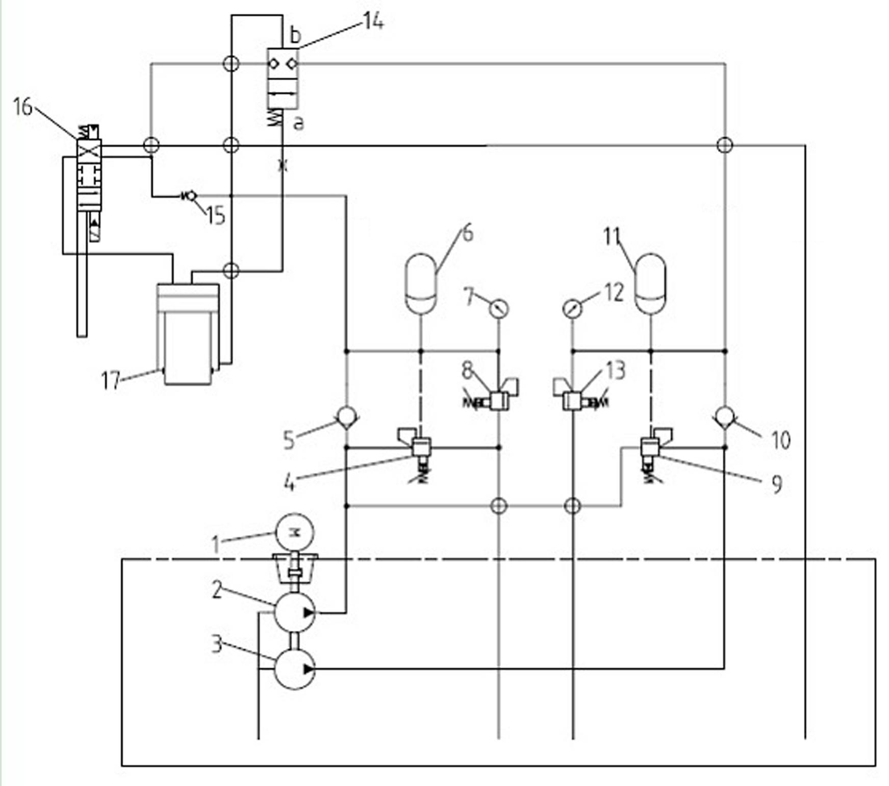
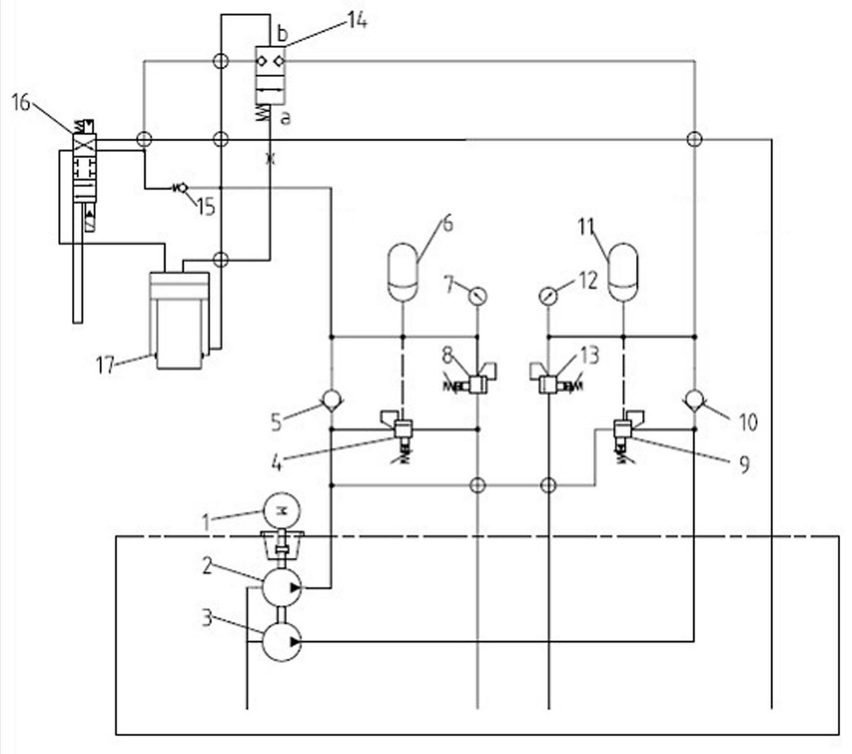
[0010] Such as figure 1 The high-speed stamping hydraulic circuit of the hydraulic stamping machine shown includes motor 1, low-pressure pump 2, high-pressure pump 3, low-pressure unloading valve 4, check valve 5, low-pressure accumulator 6, pressure gauge 7, safety valve 8, high-pressure Unloading valve 9, one-way valve 10, high-pressure accumulator 11, pressure gauge 12, safety valve 13, on-off valve 14, one-way valve 15, reversing valve 16 and oil cylinder 17.

[0011] Low-pressure unloading valve 4, one-way valve 5, low-pressure accumulator 6, pressure gauge 7, safety valve 8 and one-way valve 15 are connected to form a low-pressure loop through oil pipes, and one end of the low-pressure loop is connected to low-pressure pump 2.

[0012] High-pressure unloading valve 9, check valve 10, high-pressure accumulator 11, pressure gauge 12, safety valve 13 and on-off valve 14 are connected to form a high-pressure circuit through oil pipes, and one end of the high-pressure circuit...


PUM


Abstract

The invention discloses a high-speed punching hydraulic circuit of a hydraulic punching machine. The high-speed punching hydraulic circuit comprises an oil cylinder, a high-voltage circuit, a low-voltage circuit, a change valve, a high-voltage pump used for supplying oil to the high-voltage circuit and a low-voltage pump used for supplying oil to the low-voltage circuit; the change valve is used for changing directions of an upper cavity of the oil cylinder, a pipeline formed after the high-voltage circuit and the low-voltage circuit are converged, and a return pipeline; a low-voltage energy accumulator, a one-way valve and a low-voltage unloading valve are arranged on the low-voltage circuit; a lower cavity of the oil cylinder is connected with the low-voltage circuit; a high-voltage unloading valve, a one-way valve, a high-voltage energy accumulator and a directly-operated type balanced normally open logic valve are arranged on the high-voltage circuit; an oil discharge outlet of the logic valve is connected with the upper cavity of the oil cylinder, and a pressure guide hole of the logic valve is connected with the lower cavity of the oil cylinder; and an oil outlet of the high-voltage unloading valve is connected with the low-voltage circuit. According to the high-speed punching hydraulic circuit of the hydraulic punching machine, the opening and the closing of the logic valve are controlled through pressure change of the upper and lower cavities of the oil cylinder, so that the connection of the high-voltage circuit is controlled, and automatic connection and disconnection of pressure oil from the high-voltage circuit to the low-voltage circuit can be implemented.

Description

technical field [0001] The invention relates to a hydraulic circuit, in particular to a hydraulic circuit for controlling stamping oil cylinders. Background technique [0002] Because of the intermittent use of hydraulic stamping machine tools, accumulators are used in the hydraulic circuit to achieve work as an auxiliary energy source to increase the stamping speed, store the pressure oil output by the hydraulic pump during intermittent periods, and cooperate with the unloading valve when the pressure reaches the design pressure Unload the circuit hydraulic pump to achieve the purpose of energy saving. At present, high-speed stamping circuits are mostly used in pure high-pressure circuits and low-pressure circuits with accumulators and high-pressure circuits without accumulators. The stamping speed of the pure high-pressure circuit is fast, but the power consumption is high, the heat generation is large, and the high-pressure operation will have a great impact on the pipel...

Claims


Application Information

Patent Timeline
Patent Type & Authority Applications(China)
IPC IPC(8): F15B21/08F15B1/02B21D22/00
Inventor 刘仲湖
Owner SHANDONG FIN CNC MACHINE
Why Eureka
Try Eureka