Transmission hydraulic control system having flow augmentation

A technology of hydraulic control system and transmission, applied in the direction of components with teeth, transmission control, belt/chain/gear, etc., which can solve the problem that the main pump cannot provide hydraulic fluid pressure level and other problems

Inactive Publication Date: 2012-07-18
GM GLOBAL TECH OPERATIONS LLC
View PDF8 Cites 8 Cited by
  • Summary
  • Abstract
  • Description
  • Claims
  • Application Information

AI Technical Summary

Problems solved by technology

However, since the prime mover is shut down, the main pump is unable to provide the required hydraulic fluid pressure level

Method used


Image

  • Transmission hydraulic control system having flow augmentation
  • Transmission hydraulic control system having flow augmentation
  • Transmission hydraulic control system having flow augmentation

Examples


Embodiment Construction

[0057] The following description is merely exemplary in nature and is not intended to limit the invention, its application or uses.

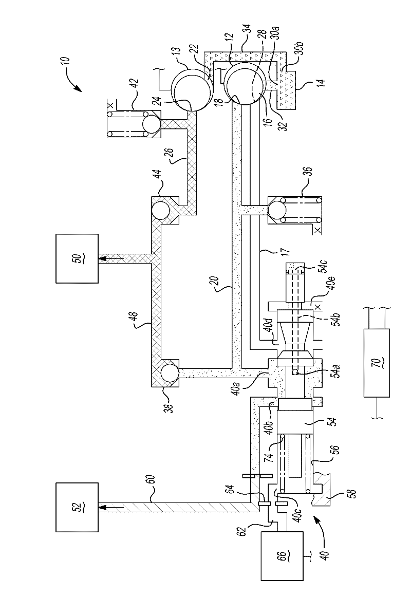
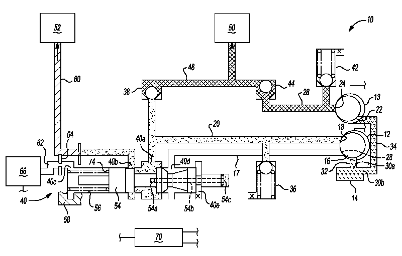
[0058] refer to figure 1 , a subsystem of a hydraulic control system for a transmission of a motor vehicle is indicated generally with reference numeral 10 . Subsystem 10 operates as a source of pressurized hydraulic fluid for the hydraulic control system and includes a main pump 12 and an auxiliary pump 13 both in fluid communication with a sump 14 . The pump 12 can be driven directly by the internal combustion engine in the motor vehicle, or by an electric motor or other prime mover. Pump 12 includes an inlet port 16 and an outlet port 18 . Inlet port 16 communicates with sump 14 and fluid return line 17 and outlet port 18 communicates with a low pressure branch or supply line 20 . Pump 12 may be of various types, such as a gear pump, vane pump, rotary pump, or any other positive displacement pump.

[0059] The auxiliary pump 13 is driven ...


PUM


Abstract

A system for providing pressurized hydraulic fluid includes an engine driven main pump and an electrical motor driven auxiliary pump. The auxiliary pump provides hydraulic fluid at line pressure to shift control subsystems during a vehicle launch while the main pump provides hydraulic fluid to cooler or lubrication subsystems during the vehicle launch. A pressure regulation valve regulates the pressure of the hydraulic fluid from the main pump. Once the main pump reaches a critical speed, the main pump provides hydraulic fluid at line pressure to the hydraulic control system and the auxiliary pump is turned off.

Description

[0001] Cross References to Related Applications [0002] This application claims the benefit of US Provisional Application No. 61 / 432,140, ​​filed January 12, 2011. The entire content of the above application is incorporated herein by reference. technical field [0003] The present invention relates to hydraulic control systems for transmissions, and more particularly to electrohydraulic control systems having a main pump, an auxiliary pump, and a mechanism to increase pump flow. Background technique [0004] This section merely provides background information related to the present disclosure and may or may not constitute prior art. [0005] A typical automatic transmission includes a hydraulic control system that is used, among other functions, to actuate a number of torque-transmitting devices. These torque-transmitting devices may be, for example, friction clutches and brakes. Conventional hydraulic control systems typically include a main pump that provides a pressur...

Claims


Application Information

Patent Timeline
Patent Type & Authority Applications(China)
IPC IPC(8): F16H61/435F16H61/44F16H61/4165
CPCF16H61/0031
Inventor Z.谢H.杨A.L.史密斯J.M.哈特S.P.穆尔曼
Owner GM GLOBAL TECH OPERATIONS LLC
Why Eureka
Try Eureka