Mechanical sealing structure with flower and plant simulating fluid type groove end surfaces

An end face mechanical seal and mechanical seal technology, applied in the direction of engine seals, mechanical equipment, engine components, etc., can solve problems such as unsatisfactory start-up performance or low-speed and low-pressure performance, fluid film bearing capacity and rigidity limitations, etc., to improve dynamic pressure Opening characteristics, safe and reliable sealing operation, and enhanced stability

Active Publication Date: 2012-07-18
ZHEJIANG UNIV OF TECH
View PDF17 Cites 8 Cited by
  • Summary
  • Abstract
  • Description
  • Claims
  • Application Information

AI Technical Summary

Problems solved by technology

[0003] In order to overcome the problems of unsatisfactory start-up performance or low-speed and low-pressure performance of the seal existing in the existing bidirectional rotary groove end mechanical seal structure, and the limited bearing capacity and rigidity of the fluid film, the present invention provides a flower-like fluid type groove end mechanical seal sealed structure

Method used


Image

  • Mechanical sealing structure with flower and plant simulating fluid type groove end surfaces
  • Mechanical sealing structure with flower and plant simulating fluid type groove end surfaces
  • Mechanical sealing structure with flower and plant simulating fluid type groove end surfaces

Examples


Embodiment 1

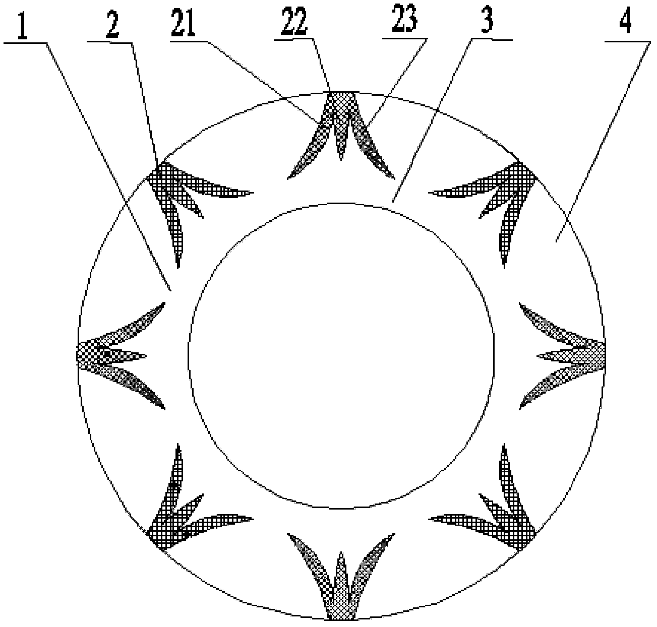
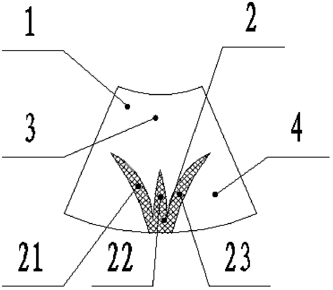
[0031] refer to Figure 1-2 , a mechanical seal structure imitating flowers and grass fluid type groove end faces, including a moving ring and a static ring of a mechanical seal, one side of the end faces of the moving ring and the static ring is the high pressure side, that is, the upstream, and the end faces of the moving ring and the static ring The other side is the low-pressure side, that is, the downstream, and the downstream of the end face is provided with a smooth and flat annular seal dam 3, which is characterized in that at least one end face of the moving ring or static ring is provided with a plurality of uniformly distributed circumferential seals. The drainage groove 22 and the left and right grooves 21, 23 centered on the drainage groove 22 form a fluid-type groove 2 similar in shape to flowers and plants. The drainage groove 22 is a radial groove, and the fluid-type groove 2 is distributed in accordance with On an annular belt at the center of the end surface ...

Embodiment 2

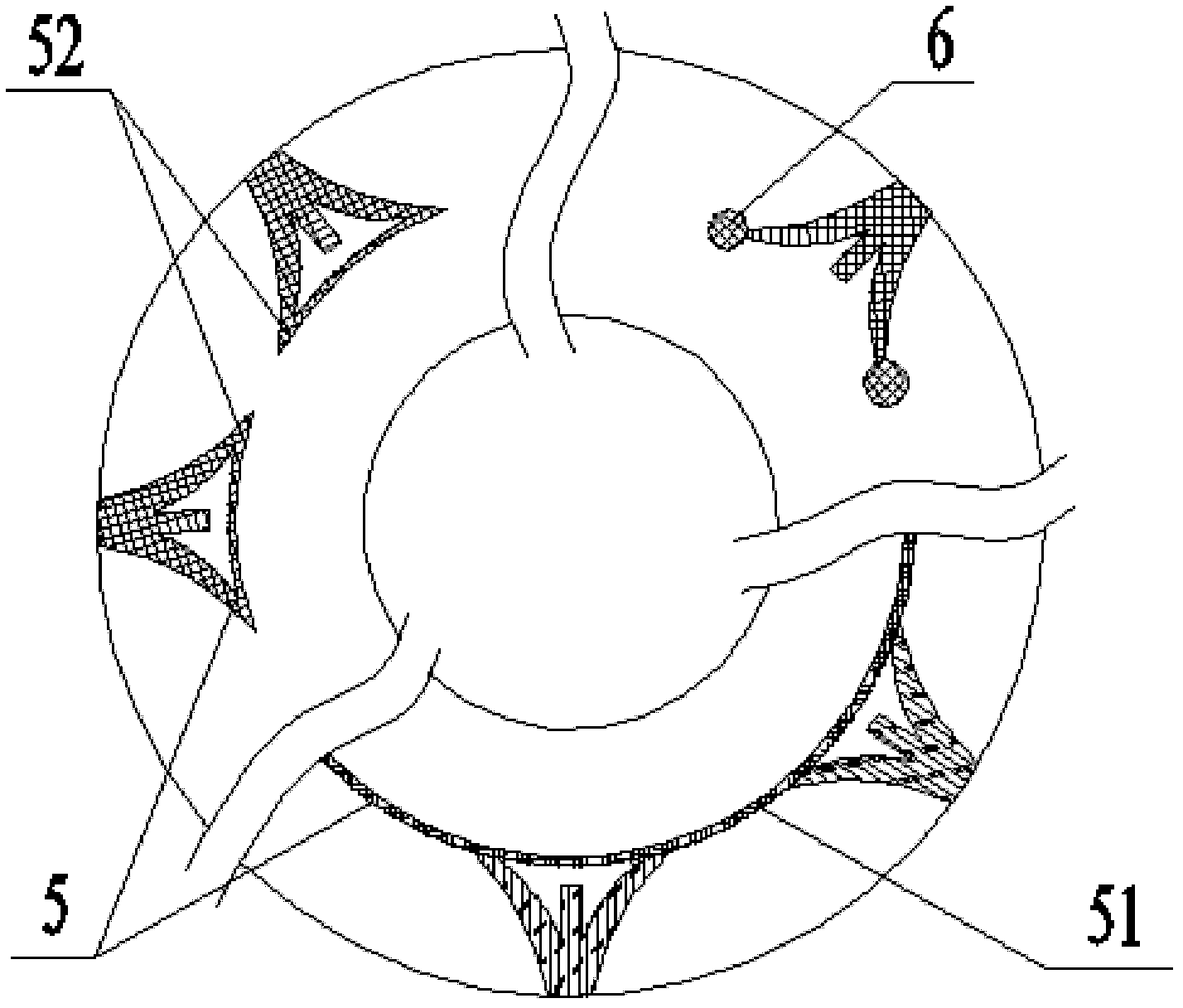
[0041] refer to image 3 The difference between the present embodiment and the first embodiment is that the downstream end of the imitation flowers and plants fluid type groove is connected with other type grooves 5 or type holes 6, so as to improve the pressure distribution in the circumferential direction of the end surface where the root of the groove is located and in the vicinity thereof Uniformity, enhance the hydrodynamic pressure effect, improve the rigidity of the fluid film, improve the start-up characteristics of the seal and the ability to operate at low speed and low pressure, and improve the wear resistance of the end face.

[0042] Described type groove 5 can be circular groove 51, arc groove 52 etc. type line groove, and the width and depth of described type groove 5 are respectively w a and h a , the value range is: w a =0.5~2.0mm, h a =h g / 10~h g / 5, where h g It is the depth of imitation flowers and plants fluid type groove; Described type hole 6 is m...

Embodiment 3

[0044] refer to Figures 4a-4c , The difference between this embodiment and Embodiment 1 is that the fluid-type groove presents a convergent stepped structure with a deep upstream and a shallow downstream. The convergent fluid groove can be one step, two steps or multiple steps, but in order to control the processing cost, it is generally better to use two or three steps under the premise of satisfying a certain cost performance. The minimum depth of the downstream side of the groove should not be less than 1.5μm (dry gas seal) or 0.1mm (liquid seal); in addition, in the case of higher requirements for sealing stability and end surface lubricity, a convergent inclined step structure can also be used. The inclination angle of the inclined steps is 2-10 degrees. The flower-like fluid type groove end face mechanical seal with a convergent step structure is to meet the needs of applications such as low speed or long start-up process or sudden changes in operating conditions, so a...


PUM


Abstract

The invention discloses a mechanical sealing structure with flower and plant simulating fluid type groove end surfaces. The mechanical sealing structure comprises a mechanical sealing movable ring and a mechanical sealing stationary ring; one sides of the end surfaces of the movable ring and the stationary ring are high-pressure sides, i.e. advanced positions; the other sides of the end surfaces of the movable ring and the stationary ring are low-pressure sides, i.e. backward positions; the backward positions of the end surfaces are provided with circular sealing dams with smooth flat surfaces; the mechanical sealing structure is characterized in that a plurality of fluid type grooves, which are uniformly distributed along the circumference direction, are formed by drainage grooves, left profiled grooves and right profiled grooves centering around the drainage grooves and take the shape of flowers and plants in appearance, are arranged on at least one of the end surfaces of the movable ring and the stationary ring, the drainage grooves are radial grooves; the fluid type grooves are distributed on an annular belt in accordance with the centers of the end surfaces, the circular belt is arranged at the advanced positions of the end surfaces; and no slotting regions between the flower and plant simulating fluid type grooves form a sealing weir. The mechanical sealing structure has better fluid guiding effect; the pressures of the root regions of the fluid type grooves are higher and more uniformly distributed; and the bearing capacity of a seal and the rigidity of a fluid membrane are increased.

Description

technical field [0001] The invention relates to a non-contact end face sealing structure of a rotary fluid machine, in particular to a non-contact end face sealing device with a two-way rotating imitation flower-plant fluid groove end face mechanical seal structure, which is suitable for various compressors and pumps And the shaft end sealing device of the rotary shaft of the rotating machine such as the stirrer for the kettle. Background technique [0002] Shaft end seals (such as mechanical seals, packing seals, labyrinth seals, etc.) are indispensable basic components in various fluid machinery, power machinery and other rotating machinery. At present, the non-contact mechanical seal has become the preferred shaft end seal for high-parameter rotary fluid machinery due to its outstanding features and advanced performance such as non-contact, no wear, low energy consumption, high pressure resistance and high stability. Two-way rotatable end face seals have been reported, s...

Claims


Application Information

Patent Timeline
Patent Type & Authority Applications(China)
IPC IPC(8): F16J15/34
Inventor 彭旭东许静白少先李纪云盛颂恩
Owner ZHEJIANG UNIV OF TECH
Why Eureka
Try Eureka