
Compound sealing device

A sealing device and composite sealing technology, which is applied to the sealing of the engine, engine components, mechanical equipment, etc., can solve the problems of medium leakage, high processing precision, and adding rigid material support rings, etc., to achieve low medium leakage and small medium leakage , good sealing effect

Inactive Publication Date: 2012-07-18
BEIJING NIUXI HYDRAULIC TECH INST
View PDF7 Cites 1 Cited by
  • Summary
  • Abstract
  • Description
  • Claims
  • Application Information

AI Technical Summary

Problems solved by technology

Its sealing mechanism is basically the same as the sealing technology of elastic material seals such as O-rings and Yx-rings. They are not real elastic material sealing technologies. There has always been a problem of medium leakage, and the sealing effect is not very satisfactory. very high pressure
There will also be instability caused by the rigid material ring support, which makes the existing main engine prone to work failures during operation
Especially when two or more combined sealing elements are used at the same time, the number of rigid material support rings is actually increased, which is more likely to cause work failures, increases the difficulty of manufacturing and processing the main engine, requires high processing precision, and causes the cost of the main engine to increase significantly
Not only the economic benefits are poor, but also the consumption of material resources is large

Method used


Image

  • Compound sealing device
  • Compound sealing device
  • Compound sealing device

Examples


Embodiment Construction

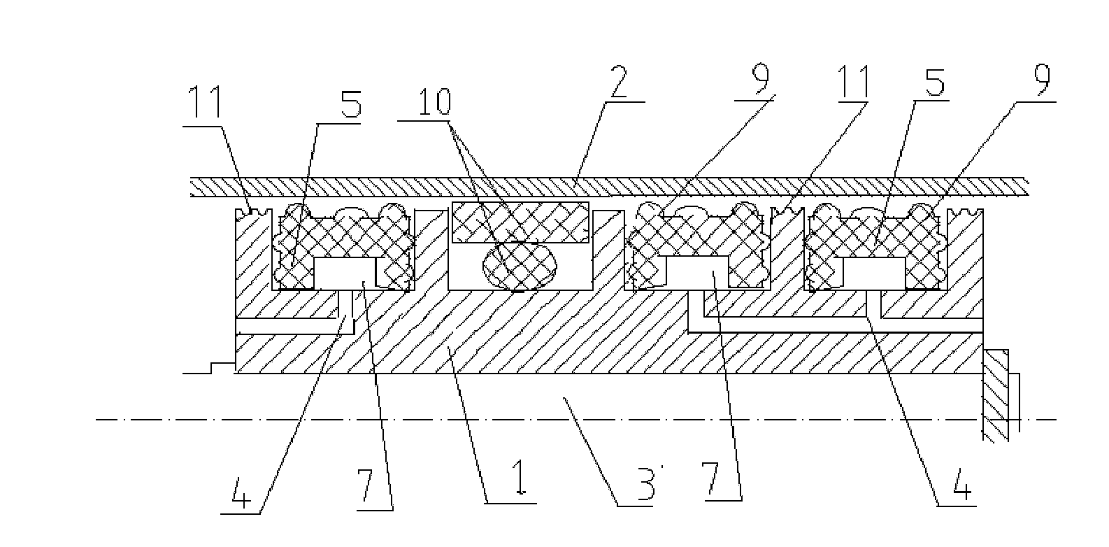
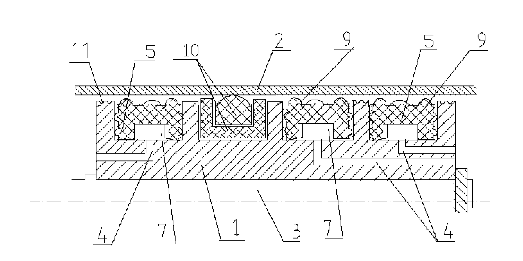
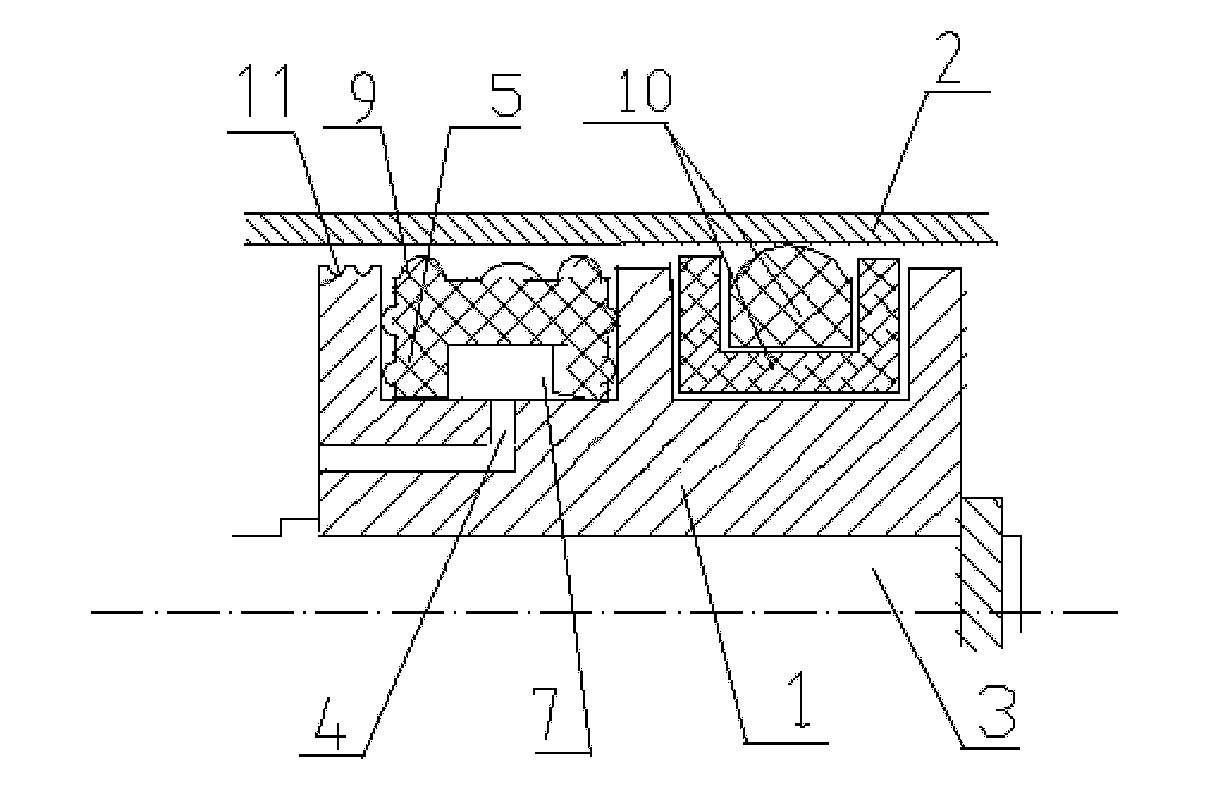
[0022] From figure 1 , figure 2 , image 3 and Figure 4 It can be seen from the figure that when the sealing device of the present invention is used as a shaft sealing device, a certain amount of space is added to the end of the existing O-ring, Yx-ring or combined sealing element 10 on the sealing device block 1 close to the direction of action of the working medium. The n-shaped sealing ring is placed in the groove, and the n-shaped sealing ring 5 for the shaft is installed in each groove; the end surface of the sealing device block 1 near the end of the working medium action direction is provided with a passage hole 4 for guiding the medium into the inner cavity 7 of each sealing ring, The medium can be introduced into the inner chamber 7 of the n-ring seal 5 for the shaft. Since the n-shaped sealing ring 5 is at the end of the composite sealing device close to the action direction of the working medium, the n-shaped sealing ring 5 first plays a sealing role. After th...


PUM


Abstract

The invention discloses a compound sealing device, which is low in medium leakage rate, resistant to pressure and long in service life. The compound sealing device is formed by adding n-shaped sealing rings on an existing sealing device with an O-shaped ring, a Yx-shaped ring or a combination sealing element. As the inner cavities of the n-shaped sealing rings are hollow, the sealing force in the inner cavities of the n-shaped sealing rings directly comes from the working medium pressure; therefore, the working medium pressure in the inner cavity (7) of the n-shaped sealing ring (5) is in a self dynamic balance state at any time during the working period of a host; and the working status of the original O-shaped ring, the Yx-shaped ring or the combination sealing element are not affected. The compound sealing device simultaneously has the sealing processing property of the n-shaped sealing rings (5, 6), the O-shaped ring, the Yx-shaped ring or the combination sealing element (10), is low in medium leakage, resistant to a high pressure and long in service life and can be used as a piston sealing device and an end cover sealing device of various hydraulic plants. The compound sealing device can be used only by simply reforming and processing the existing sealing device adopting the O-shaped ring, the Yx-shaped ring or the combination sealing element.

Description

technical field [0001] The invention relates to a sealing device, in particular to a composite sealing device. It belongs to the technical field of fluid transmission sealing. Background technique [0002] Sealing technology is of great significance to prevent "three leaks" (oil, gas, water) of electromechanical products and equipment, ensure safe operation, improve work performance and efficiency, save energy and protect the environment. [0003] As we all know, traditional rubber sealing devices such as O-rings, Yx-rings, and U-rings are commonly used at present to achieve sealing by extruding the sealing ring from the outside of the sealing ring body. When the working pressure exceeds a certain value, the rubber sealing element will produce Yield deformation, the working medium will pass through the sealing belt to cause medium leakage and make the seal invalid, which will gradually lead to a decrease in equipment working efficiency, increased energy consumption, polluti...

Claims


Application Information

Patent Timeline
IPC IPC(8): F16J15/447F16J15/46F16J15/16
CPCF16J15/48
Inventor 周承惠周磊张相新张相安
Owner BEIJING NIUXI HYDRAULIC TECH INST
Learn More