Separable ignition device

An ignition device, a separate technology, applied in rocket launchers, launchers, offensive equipment and other directions, can solve the problems of low burning rate, small initial burning surface of the main charge, incomplete burning, etc., to expand the application field, Enhanced safety and stability, reduced mechanical properties

Inactive Publication Date: 2012-07-18
BEIJING MECHANICAL EQUIP INST
View PDF3 Cites 2 Cited by
  • Summary
  • Abstract
  • Description
  • Claims
  • Application Information

AI Technical Summary

Problems solved by technology

[0003] The purpose of the present invention is to provide a detachable ignition device, which solves the instability factors of misignition in current igniters, as well as the problems of small initial burning surface, low burning speed and incomplete combustion of the main charge.

Method used


Image

  • Separable ignition device
  • Separable ignition device
  • Separable ignition device

Examples


Embodiment Construction

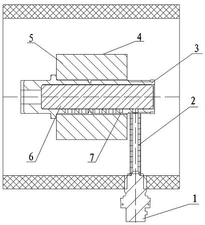
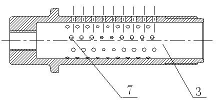
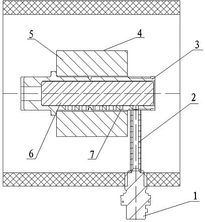
[0010] A detachable ignition device, comprising: ignition powder 6, also includes: fire transmission tube 2, ignition tube 3, ignition powder box 4, insensitive ignition head 1. The insensitive ignition head 1 is columnar, the fire transfer tube 2 is a round tube, one end of the fire transfer tube 2 is placed on the insensitive ignition head 1, and is connected with coaxial threads, the axis of the fire transfer tube 2 is perpendicular to the axis of the ignition tube 3, The other end of the fire tube 2 is screwed to the side wall of the ignition tube 3 . The ignition powder 6 is placed inside the ignition tube 3, and there are a plurality of fire transmission holes 7 on the outer surface of the ignition tube 3 in a direction perpendicular to the axis. The main charge 5 is placed in the ignition cartridge 4, and the ignition tube 3 is placed in the hole of the ignition cartridge 4 and in close contact.

[0011] When the ignition device is working, the ignition current detonat...


PUM


Abstract

The invention discloses a separable ignition device which comprises ignition composition (6) and also comprises an fire transferring tube (2), an ignition tube (3), an ignition composition box (4) and an insensitive ignition head (1), wherein one end of the fire transferring tube (2) is arranged on the insensitive ignition head (1) in coaxial threaded connection; the axis of the fire transferring tube (2) is vertical to the axis of the ignition tube (3); the other end of the fire transferring tube (2) is in coaxial threaded connection with the side wall of the ignition tube (3); and the ignition composition (6) is arranged at the inner part of the ignition tube (3). When the ignition device works, the insensitive ignition head (1) is detonated and ignited by utilizing ignition current; the generated fire is transferred into the ignition tube (3) through the fire transferring tube (2) to ignite the ignition composition (6) in the ignition tube (3); the ignition composition (6) rapidly burns beginning from the outside surface; the ignition composition box (4) is burned out by the fire; and main charge (5) is ignited. The separable ignition device has the advantages that the safety and the stability of the system are enhanced, and the sufficiency of main charge ignition is realized.

Description

technical field [0001] The invention relates to an ignition device, in particular to a detachable ignition device. Background technique [0002] There are three types of ignition devices used in missile rockets: ignition head, electric detonator and igniter. The igniter widely used at present is made up of igniter, igniter shell, ignition wire, and principle is to ignite igniter by ignition current, and the flame that igniter produces ignites the main charge of missile rocket again. The igniter has unstable factors such as misignition, and the main charge is not fully ignited, the initial burning area is small, the burning speed is low, and the burning is not complete. Contents of the invention [0003] The purpose of the present invention is to provide a detachable ignition device, which can solve the problems of misignition instability, small initial burning area, low burning speed and incomplete combustion of the main charge in current igniters. [0004] A detachable ...

Claims


Application Information

Patent Timeline
Patent Type & Authority Applications(China)
IPC IPC(8): F41F3/04F41F7/00
Inventor 苏成帅陈爱锋韩书永
Owner BEIJING MECHANICAL EQUIP INST
Why Eureka
Try Eureka