Supercharge Your Innovation With Domain-Expert AI Agents!

Measuring device and measuring method of concrete viscosity

A technology of measuring devices and measuring methods, applied in measuring devices, flow characteristics, instruments, etc., can solve the problems of high cost, complicated instrument structure, inaccurate measurement of shear torque, etc., and achieve the effect of simple structure and easy operation

Active Publication Date: 2014-06-18
HARBIN INST OF TECH
View PDF6 Cites 0 Cited by
  • Summary
  • Abstract
  • Description
  • Claims
  • Application Information

AI Technical Summary

Problems solved by technology

[0003] The present invention solves the problem that when existing rheometers and viscometers measure the rheological parameters of concrete, it is easy to separate the aggregate from the slurry, and the concrete cannot form a stable homogeneous laminar flow state. The measurement is not very accurate, the instrument structure is complicated, and the cost is high, and then a measuring device and method for measuring the viscosity of concrete is proposed

Method used


Image

  • Measuring device and measuring method of concrete viscosity

Examples


specific Embodiment approach 1

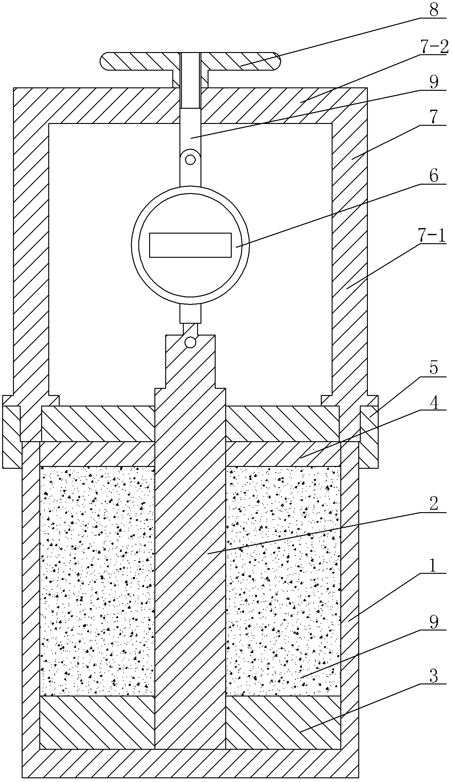
[0012] Specific implementation mode one: combine figure 1 Describe this embodiment mode, a kind of concrete viscosity measuring device described in this embodiment mode comprises container 1, steel cylinder 2, tray 3, pressure plate 4, container cover 5 and electronic scale 6, and tray 3 is arranged on the inner cavity of container 1 On the bottom surface, the pressure plate 3 is arranged at the container mouth of the container 1, the lower end of the steel cylinder 2 passes through the center hole of the tray 3, and the lower end surface of the steel cylinder 2 is in contact with the bottom surface of the inner cavity of the container 1, and the steel cylinder 2 The upper end passes through the central hole of the pressure plate 4 and the central hole of the container cover 5 successively from bottom to top, and the upper end of the steel cylinder 2 is connected with the lower end of the electronic scale 6 by pins, and the outer wall of the steel cylinder 2 is provided with th...

specific Embodiment approach 2

[0013] Specific implementation mode two: combination figure 1 To illustrate this embodiment, a concrete viscosity measuring device described in this embodiment also includes a bracket 7, a hand wheel 8 and a screw 9, and the bracket 7 is a door composed of two columns 7-1 and a beam 7-2 Glyph support 7, the lower end of each column 7-1 is respectively inserted in the corresponding hole on the edge of container cover 5, the lower end of screw rod 9 is connected with the upper end of electronic scale 6 by pin, and the upper end of screw rod 9 passes crossbeam 7- The through hole in 2 middle parts is connected with handwheel 8. Other components and connections are the same as those in the first embodiment.

specific Embodiment approach 3

[0014] Specific implementation mode three: combination figure 1 To illustrate this embodiment, the tray 3 and the pressure plate 4 of a concrete viscosity measuring device described in this embodiment are both made of engineering plastics. Other compositions and connections are the same as those in Embodiment 1 or 2.


PUM


Abstract

A measuring device and a measuring method of concrete viscosity relate to measuring devices and measuring methods and aim at resolving the problem that the existing rheometer and viscosity meter are apt to separate aggregate and slurry, cannot enable concrete to form stable and homogeneous laminar states and are not accurate in measurement of shearing moment when measuring concrete rheology parameter and the appliances are complex in structure and high in construction cost. The measuring device comprises a container, a steel cylinder, a tray, a press disc, a container cover and an electronic scale. The tray is arranged on the bottom face of a container inner cavity, the press disc is arranged at the position of a container opening of the container, the lower end of the steel cylinder penetrates through a center hole of the tray, the upper end of the steel cylinder sequentially penetrates through a center hole of the press disc and the center hole of the container cover from bottom to top, the upper end of the steel cylinder is connected with the lower end of the electronic scale through a dowel, and threads are arranged on the outer lateral wall of the steel cylinder. The measuring device and the measuring method are used for measuring viscosity of concrete.

Description

technical field [0001] The invention relates to a measuring device and a measuring method, in particular to a measuring device and a measuring method for concrete viscosity. Background technique [0002] The measurement method of the rheological properties of fresh concrete, according to the theory proposed by the famous scholar Bingham, at least needs to measure the yield stress viscosity and plastic viscosity of concrete. In order to measure these two parameters, foreign scholars have made a lot of improvements to the existing traditional viscometer. The famous scholar G.H.Tattersall and his students had designed different types of stirring paddles. Scholars in Japan and Europe have also changed the structure of the existing viscometer and done a lot of experimental work. However, the experimental reports and related curves of the rheological parameters of scholars from various countries are far from each other, and the conclusions of the experimental reports are very inc...

Claims


Application Information

Patent Timeline
Patent Type & Authority Patents(China)
IPC IPC(8): G01N11/14
Inventor 杨英姿高小建邓宏卫
Owner HARBIN INST OF TECH
Features
  • R&D
  • Intellectual Property
  • Life Sciences
  • Materials
  • Tech Scout
  • Unparalleled Data Quality
  • Higher Quality Content
  • 60% Fewer Hallucinations
Learn More