
LED (light emitting diode) service life test system and test method thereof

A technology for life testing and subsystems, applied in the LED fixed part, the structure of the hot and cold dual-zone temperature box, and the field of refrigerators, can solve the problems of increasing the test uncertainty, increasing the aging cost, and failing to achieve the test purpose. Improve reliability and continuity, improve test efficiency, facilitate the effect of failure causes

Inactive Publication Date: 2012-07-18
常州市产品质量监督检验所 +1
View PDF4 Cites 28 Cited by
  • Summary
  • Abstract
  • Description
  • Claims
  • Application Information

AI Technical Summary

Problems solved by technology

This brings about several problems: First, repeated disassembly and installation requires a lot of labor and time, which dramatically increases the cost of aging and wastes time; second, repeated disassembly and installation can easily damage the LED, increasing the uncertainty of the entire test , that is to say, the tester may not be able to judge whether the damage of a certain LED is caused by human factors during the disassembly process or the product quality of the LED itself, which cannot achieve the purpose of the test; moreover, it is very easy during the disassembly and installation process Stains and scratches on the optical lens of the LED will affect its light output characteristics, thereby affecting the measurement results and causing deviations in the calculation results
However, after the LED is lit, the temperature will rise sharply, resulting in a huge temperature difference between the surface and the surrounding air.

Method used


Image

  • LED (light emitting diode) service life test system and test method thereof
  • LED (light emitting diode) service life test system and test method thereof
  • LED (light emitting diode) service life test system and test method thereof

Examples


Embodiment Construction

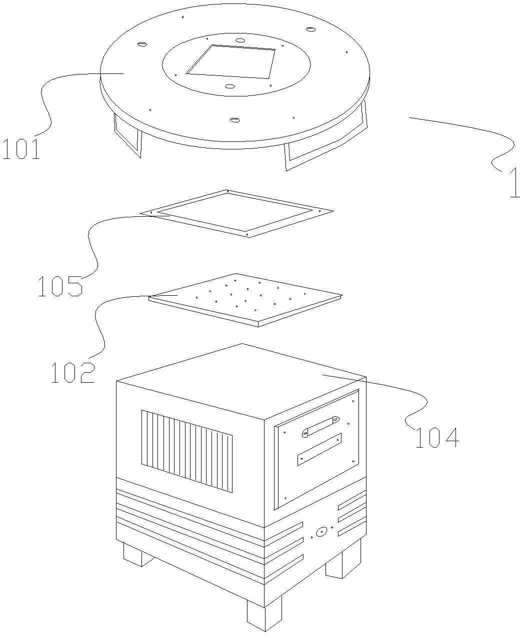
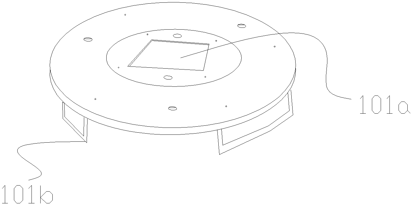
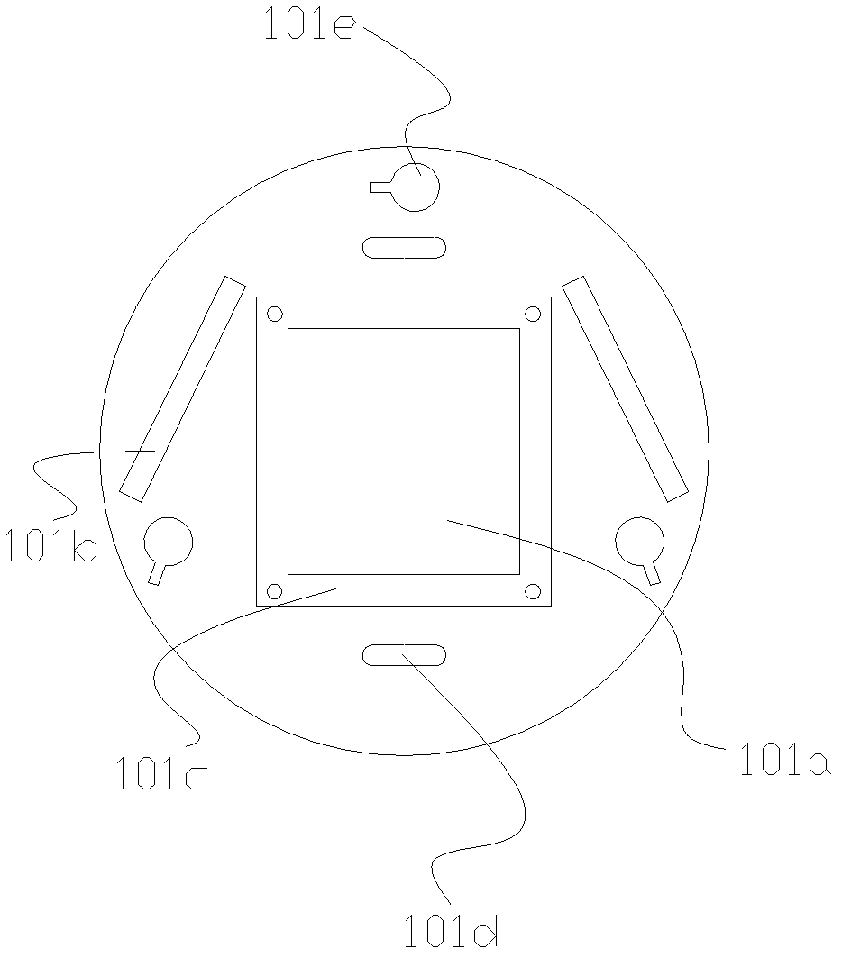
[0042] The LED life test system of the present invention includes an aging subsystem that uses a cold and hot dual-zone temperature box for aging and a measurement subsystem that uses an integrating sphere for photochromic and electrical measurements, and also includes such as figure 1 The cooler 1 shown and as Figure 4 The shown aluminum substrate 3 for welding multiple LEDs to be tested, such as Figures 1 to 4 As shown, the refrigerator 1 includes a mounting plate 101, an electric cooling plate 102 and a radiator 104, the electric cooling plate 102 and the mounting plate 101 are fixedly installed on the radiator 104, and the middle part of the mounting plate 101 has an opening 101a, the electric cooling plate 102 is embedded in the opening 101a (in this embodiment, the electric cooling plate 102 and the opening 101a can have a matching outline, so that the former is just embedded in the latter), and the radiator 104 is located on the side facing the bottom surface of the ...


PUM


Abstract

The invention discloses an LED (light emitting diode) service life test system, which comprises refrigerators, aluminum printed circuit boards (PCBs), a cold and hot two-region temperature box and an integrating sphere. An electric refrigerating plate and a subpanel of the refrigerator are fixedly installed on a radiator and the electric refrigerating plate is embedded into an opening of the subpanel. The aluminum PCB is fixed on the surface of the electric refrigerating plate. The cold and hot two-region temperature box comprises cold and hot boxes isolated by an insulation board. The insulation board and the integrating sphere are provided with installation holes for installing the refrigerators. When the refrigerators are respectively installed on the installation holes of the temperature box and the integrating sphere, the radiators are respectively placed outside the cold box and the integrating sphere while the aluminum PCBs are respectively placed inside the hot box and the integrating sphere. The refrigerators provided by the invention can move integrally without disassembling the LED, which facilitates the LED service life test greatly. In addition, each LED can be independently lighted by connecting a lead wire at the connection solder joint of the aluminum PCB to a switching circuit, thereby achieving the aim of testing the parameters of light, color and electricity of each LED independently.

Description

technical field [0001] The present invention relates to an LED life test system and its test method, in particular to the structure of LED fixed part, refrigerator, and cold and hot dual-zone temperature box in the LED life test system, and the test method related to the improvement of the above structure. Background technique [0002] After a single LED is produced, an evaluation of its lifespan is required. At present, the more common practice is to extract certain LED samples from a batch of LEDs of the same type and age them for thousands of hours (usually not less than 6000 hours). Before aging, test the light, color, electricity parameters of each LED, And during the aging process, measure its photochromic and electrical parameters at regular intervals; the longer the aging time, the greater the attenuation of the LED light output, save the results of each measurement, and calculate the light output of the LED after aging according to a certain algorithm Attenuation, ...

Claims


Application Information

Patent Timeline
IPC IPC(8): G01R31/44G01K7/02
Inventor 施朝阳陈云明邓恒波
Owner 常州市产品质量监督检验所
Learn More