V-component containing all-component polarized remotely-sensed imaging measurement system and method
A polarization remote sensing and imaging measurement technology, applied in the field of measurement systems, can solve the problems of synchronous acquisition, research, and inability to apply incomplete component images.
- Summary
- Abstract
- Description
- Claims
- Application Information
AI Technical Summary
Problems solved by technology
Method used
Image
Examples
Embodiment 1
[0057] Example 1: Obtaining the unique information characteristics of V component and obtaining physical components such as spectrum and intensity
[0058] 1. Under ideal light source illumination conditions in the laboratory:
[0059] 1) Irradiate the surface of the rock sample with non-polarized light and linearly polarized light with different irradiation angles, and use the polarization parameter measuring device to detect various polarization parameters of the reflected light, especially the polarization phase parameter corresponding to the V component, and ensure that the experiment has good performance. Repeatability, and continuously optimize the calculation model, reduce transmission errors and eliminate modulation errors through calculations in the experiment, so that the V component polarization image is very close to the actual characteristics of the ground object;
[0060] 2) Take the normal line of the reflecting surface of the irradiated light (rock surface) as the axi...
Embodiment 2
[0070] Embodiment 2: Obtain moving image feature parameters from a set of I, Q, U, and V four-component images
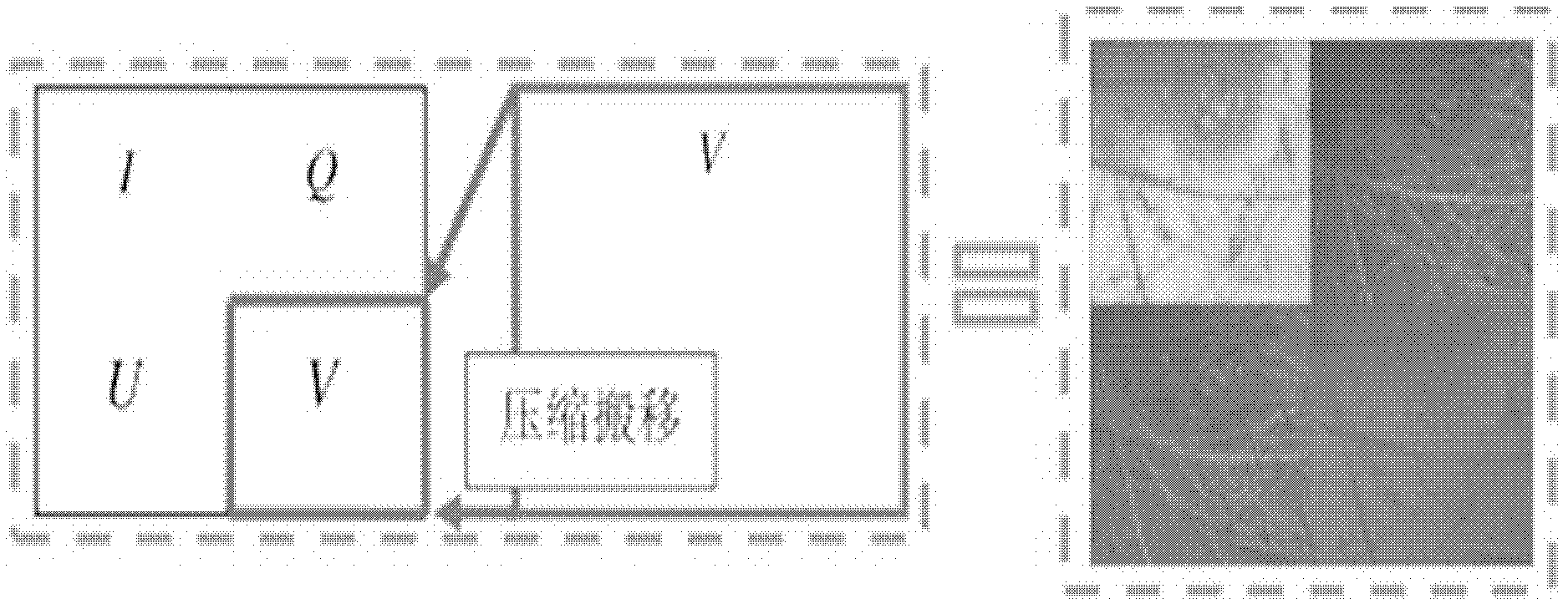
[0071] Such as Picture 9 As shown (the upper left corner is the I component imaging map, the upper right corner is the Q component imaging map, the lower left corner is the U component imaging map, and the lower right corner is the V component imaging map), you can see the existing position changes of the moving target from the four component maps , And behavior changes. By decomposing them in vector, the result of analyzing the characteristics of the moving image using the full-component imaging system is obtained, and the motion difference of the four component images in the imaging process is obtained; the position of the cyclist in each component in the figure is different, It can be seen that the direction of movement of the person is from right to left.
Embodiment 3
[0072] Embodiment 3: Acquisition of imaging parameters, delay time and degradation parameters of a full-component imaging system
[0073] 1. Four-component imaging time delay relationship and imaging richness judgment
[0074] Such as Figure 8 As shown, it can be seen from the figure that the action in each component is different, so it can be qualitatively judged that the four components are indeed time lag when imaging; in the Q component, you can almost see the entire character in the lower right corner of the car, while in the V component There are only half of them, and there are fewer people in the U component or even no people in the I component. This indicates that the four component imaging has a time difference problem, and it can be concluded that the imaging sequence is Q, V, U, I. That is to say, in the process of shooting, first the Q component is imaged first, then the V component, then U, and finally the I component.
[0075] 2. The imaging delay characteristic para...
PUM
 Abstract
Description
Claims
Application Information
 - R&D
- Intellectual Property
- Life Sciences
- Materials
- Tech Scout
- Unparalleled Data Quality
- Higher Quality Content
- 60% Fewer Hallucinations
Browse by: Latest US Patents, China's latest patents, Technical Efficacy Thesaurus, Application Domain, Technology Topic, Popular Technical Reports.
© 2025 PatSnap. All rights reserved.Legal|Privacy policy|Modern Slavery Act Transparency Statement|Sitemap|About US| Contact US: help@patsnap.com


