
Movement control method and control system of glass wiping robot

A technology of glass-wiping robot and control method, which is applied in the field of intelligent robots, can solve the problems of heavy workload, high labor intensity, repeated wiping, etc., and achieve the effect of reducing work intensity, high intelligence level, and evenly wiping glass

Active Publication Date: 2012-07-18
ECOVACS HOME SERVICE ROBOTICS CO LTD
View PDF5 Cites 12 Cited by
  • Summary
  • Abstract
  • Description
  • Claims
  • Application Information

AI Technical Summary

Problems solved by technology

[0004] Although the above technical solution effectively solves the unsafe factors that may occur when wiping the outer window, the glass cleaner needs to manually manipulate the operating part located on the inner side of the glass to guide the operating part located on the outer side of the glass to work. For large glass to be wiped, users still need to climb up and down, which is labor-intensive and heavy workload, and the process of cleaning the window is random, and there are defects such as repeated cleaning in some places and missing cleaning in some places

Method used


Image

  • Movement control method and control system of glass wiping robot
  • Movement control method and control system of glass wiping robot
  • Movement control method and control system of glass wiping robot

Examples


Embodiment 1

[0085] Such as Figure 4 As shown, the mobile control method of the glass-wiping robot specifically includes the following steps:

[0086] Step S100: start the robot;

[0087] Step S115: the robot walks forward;

[0088] Step S120: If the control unit 11 of the robot receives the signal from the sensing unit 121 at the front end of the robot, go to step S130; otherwise, go back to step S115;

[0089] Step S130: the walking unit 15 of the robot is rotated by 90°;

[0090] Step S135: the robot walks alongside;

[0091] Step S140: If the control unit 11 receives the signal from the sensing unit 121 at the front end of the robot, proceed to step S146; Step S146: the robot drives the walking unit 15 to rotate through the differential operation of the two drive motors in the drive unit 16, and after adjusting the attitude, the robot Basically parallel to the running route of step S135 and separated by a certain distance; otherwise, return to step S135.

[0092] Step S152: the r...

Embodiment 2

[0098] Such as Figure 5 As shown, on the basis of embodiment 1, the control method of embodiment 2 further includes the following steps.

[0099] The following steps are also included between step S100 and step S115:

[0100] Step S105: the acceleration sensor inside the robot adjusts the position of the robot, and corrects the positional deviation of the robot;

[0101] Step S110: the control unit 11 receives the signal from the acceleration sensor, if it judges that the robot is in an ideal state, go to step S115; otherwise, go back to step S105.

[0102] Step S121: The control unit 11 receives the signal from the sensor unit 121 at the front end. If the control unit 11 judges that the robot is in the opposite state, proceed to step S130; otherwise, proceed to step S122; where the opposite state is that the control unit receives the signal from the front end of the robot at the same time. The signals of the sensors on the left and right sides of the

[0103] Step S122: t...

Embodiment 3

[0117] Such as Figure 6 As shown, on the basis of embodiment 2, the control method of embodiment 3 further includes the following steps.

[0118] The following specific steps are also included between step S120 and step S130:

[0119] Step S123: the two driving motors in the driving unit 15 rotate in reverse, driving the traveling unit 15 to move;

[0120] Step S124: the robot walks forward;

[0121] Step S125: If the control unit 11 receives a signal from the sensing unit 121 at the front end of the robot, go to step S130; otherwise, go back to step S124.


PUM


Abstract

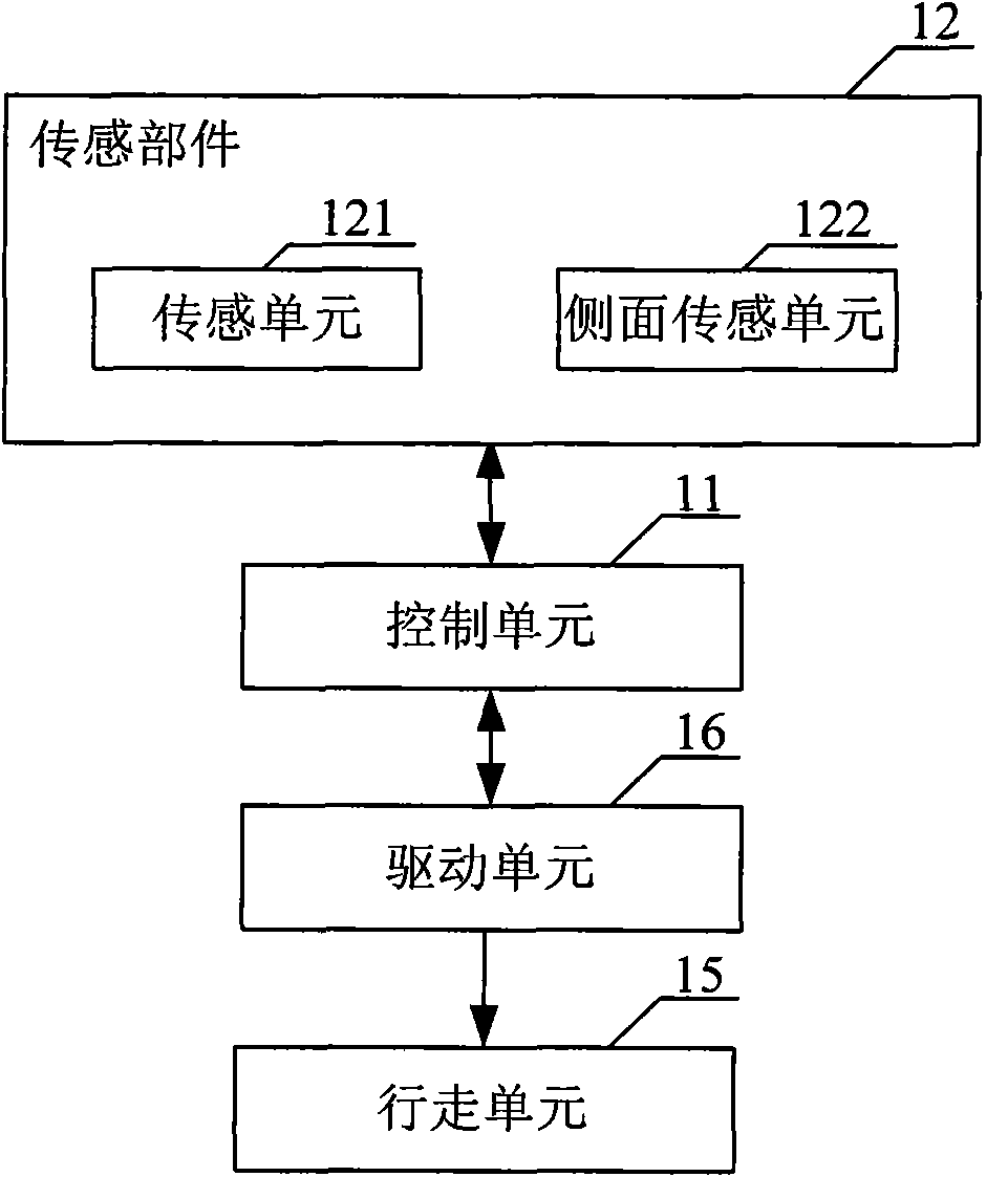
The invention belongs to the technical field of intelligent robots, and particularly relates to a movement control method and a control system of a glass wiping robot. The glass wiping robot includes a traveling unit and a driving unit. The movement control system includes a sensing part and a control unit; the sensing part includes sensing units at the same end of the glass wiping robot and side surface sensing units arranged on the side surfaces of the glass wiping robot; the control unit is connected with the sensing part and the driving unit respectively; and the control unit controls the driving unit to drive the traveling unit to move according to the signals emitted by the left and the right sensors at the same end of the intelligent robot and / or the sensors on the same side surface thereof. By adopting the movement control method and the control system of the glass wiping robot, not only can the glass be uniformly wiped, so as to relieve the working intensity of the laborers, but also the robot can avoid the blockage during the wiping process due to the high intelligence.

Description

technical field [0001] The invention belongs to the technical field of intelligent robots, and in particular relates to a movement control method and a control system of a glass-wiping robot. Background technique [0002] In daily life, for small pieces of glass, people generally use rags to clean and scrub, while large pieces of glass and the facades of windows usually use rod-type glass cleaning wipes to clean and scrub. However, when wiping glass with a pole-type glass cleaner, the arm is prone to fatigue, and when wiping outdoor glass, especially for high-rise buildings, the operation process is very dangerous. Visible, scrubbing outer window is a big difficult problem of family and even city, both unsafe and difficult to wipe completely, clean. [0003] Aiming at the above problems, a glass-cleaning device has appeared at present, and the patent number is ZL200820080547.7. figure 1 It is a schematic diagram of the structure of the existing glass-cleaning device, such ...

Claims


Application Information

Patent Timeline
Patent Type & Authority Applications(China)
IPC IPC(8): G05D1/02
Inventor 汤进举
Owner ECOVACS HOME SERVICE ROBOTICS CO LTD
Learn More