Blanking control circuit for LED (light-emitting diode) display screens and LED drive chip

A technology of LED display and blanking control, which is applied to static indicators, instruments, etc., can solve the problems of low display quality of LED display and inability to control LED constant current, so as to improve image display quality and eliminate smear phenomenon Effect

Active Publication Date: 2012-07-18
SHENZHEN SUNMOON MICROELECTRONICS
View PDF5 Cites 36 Cited by
  • Summary
  • Abstract
  • Description
  • Claims
  • Application Information

AI Technical Summary

Problems solved by technology

[0004] The purpose of the present invention is to provide a LED display screen blanking control circuit, aiming at solving the problem in the prior art that the accurate constant current control of the LED cannot be realized, resulting in low display quality of the LED display screen

Method used


Image

  • Blanking control circuit for LED (light-emitting diode) display screens and LED drive chip
  • Blanking control circuit for LED (light-emitting diode) display screens and LED drive chip
  • Blanking control circuit for LED (light-emitting diode) display screens and LED drive chip

Examples


Embodiment 1

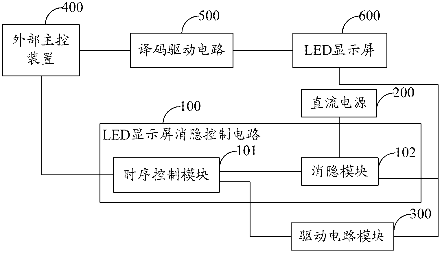
[0021] figure 1 It shows the module structure diagram of the LED display screen blanking control circuit provided by the first embodiment of the present invention. For the convenience of explanation, only the parts related to the first embodiment of the present invention are shown, and the details are as follows:

[0022] The LED display screen blanking control circuit 100 is connected with the DC power supply 200, the drive circuit module 300 and the external main control device 400, and the LED display screen blanking control circuit 100 includes:

[0023] Timing control module 101, the input end is connected with the enable signal end of external main control device 400, and the first output end is connected with the enable end of drive circuit module 300, is used for the enable control signal output from external main control device 400 Timing processing is performed, and the working state of the driving circuit module 300 is controlled through the first output terminal. ...

Embodiment 2

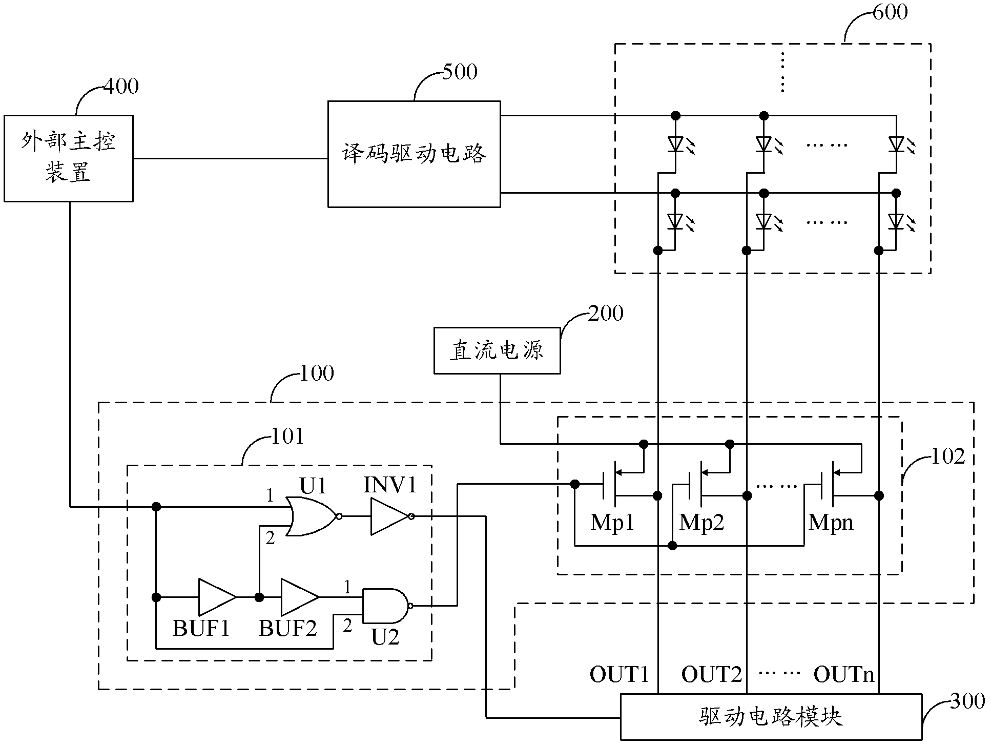
[0027] figure 2 An example circuit structure diagram of the LED display screen blanking control circuit provided by the second embodiment of the present invention is shown. For the convenience of explanation, only the parts related to the second embodiment of the present invention are shown, and the details are as follows:

[0028] As an embodiment of the present invention, the timing control module 101 includes:

[0029] The first NOR gate U1, the first inverter INV1, the first buffer BUF1, the second buffer BUF2 and the NAND gate U2;

[0030] The first input terminal 1 of the first NOR gate U1 is the input terminal of the timing control module 101, the output terminal of the first NOR gate U1 is connected to the input terminal of the first inverter INV1, and the output terminal of the first inverter INV1 is the first output terminal of the timing control module 101, the input terminal of the first buffer BUF1 is connected to the first input terminal 1 of the first NOR gate...

Embodiment 3

[0040] Figure 4 An example circuit structure diagram of the LED display screen blanking control circuit provided by the third embodiment of the present invention is shown. For the convenience of description, only the parts related to the third embodiment of the present invention are shown, and the details are as follows:

[0041] As an embodiment of the present invention, the timing control module 101 includes:

[0042] The second NOR gate U3, the second inverter INV2, the third buffer BUF3, the fourth buffer BUF4 and the AND gate U4;

[0043] The first input terminal 1 of the second NOR gate U3 is the input terminal of the timing control module 101, the output terminal of the second NOR gate U3 is connected to the input terminal of the second inverter INV2, and the output terminal of the second inverter INV2 is the first output terminal of the timing control module 101, the input terminal of the third buffer BUF3 is connected to the first input terminal 1 of the second NOR ...


PUM


Abstract

The invention belongs to the field of LED (light-emitting diode) drive control, and provides a blanking control circuit for LED (light-emitting diode) display screens and an LED drive chip. According to the invention, by adopting the blanking control circuit (comprising a time-sequence control module and a blanking module) for the LED (light-emitting diode) display screens, in the line scanning process of an LED display screen, the blanking module charges parasitic capacitors in each line of the LED display screen in a time gap generated by scanning every two lines of LEDs so to achieve the purpose of effectively eliminating a smearing phenomenon; meanwhile, a drive circuit module realizes the accurate constant current control on each line of LEDs on the LED display screen, so that the image display quality of the LED display screen is improved, thereby solving the problem that in the prior art, the display quality of the LED display screen is low because the accurate constant current control on LEDs can not be realized.

Description

technical field [0001] The invention belongs to the field of LED drive control, in particular to an LED display screen blanking control circuit and an LED drive chip. Background technique [0002] As LED displays are more and more widely used in our daily life and work, people have higher and higher requirements for LED displays. High refresh rate and large size are required by most users. However, the high refresh rate and large size will lead to a decrease in the clarity of the image display, and the main reason for the image clarity is the parasitic capacitance on the row and column lines of the LED display. During the row scanning process, if the current blanking If it cannot be well controlled, there will be a smear display phenomenon, which will seriously affect the clarity of the image. [0003] In view of the above problems, the prior art provides a blanking circuit, which charges the parasitic capacitance in advance during the row scanning process by adding a pull-...

Claims


Application Information

Patent Timeline
Patent Type & Authority Applications(China)
IPC IPC(8): G09G3/32
Inventor 李照华石磊符传汇陈克勇吕苏谊胡富斌
Owner SHENZHEN SUNMOON MICROELECTRONICS
Why Eureka
Try Eureka