Heat dissipation type photovoltaic terminal box

A volt junction box and heat dissipation technology, applied in the field of photovoltaic power generation, can solve the problems of cumbersome installation, high cost, and complicated results, and achieve the effects of expanding convection space, high reliability, and rapid heat dissipation

Active Publication Date: 2012-07-18
浙江正泰鑫辉光伏有限公司
View PDF4 Cites 8 Cited by
  • Summary
  • Abstract
  • Description
  • Claims
  • Application Information

AI Technical Summary

Problems solved by technology

[0003] One is that the terminal assembly is fixed on the mounting plate first, and then installed in the base of the photovoltaic junction box through the mounting plate. Not only is the result complicated and cumbersome to install, but the cost of using the mounting plate is high, and because the mounting plate occupies a certain area. Convection space will affect the heat dissipation performance of the entire photovoltaic junction box
At present, some structures adopt the design that the terminal assembly is tightly wrapped with two plastic parts and then clamped on the base. Although the mounting plate is omitted, the tight packaging of the plastic parts also results in poor heat dissipation inside the box.
[0004] Second, there is no thermal isolation measure between the upper cover of the photovoltaic junction box and the diode, so the heat generated by the diode is easy to burn the upper cover of the photovoltaic junction box

Method used


Image

  • Heat dissipation type photovoltaic terminal box
  • Heat dissipation type photovoltaic terminal box
  • Heat dissipation type photovoltaic terminal box

Examples


Embodiment Construction

[0026] The specific embodiments of the present invention will be further described below in conjunction with the accompanying drawings.

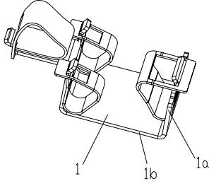
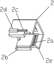
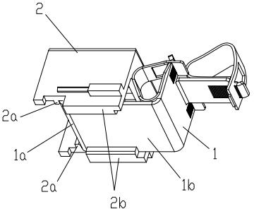
[0027] The present invention consists of the following parts: a terminal assembly 1 , a support 2 , a photovoltaic junction box base 3 , a photovoltaic junction box upper cover 4 , and a diode 5 . Among them, the typical structure of the terminal assembly 1 consists of figure 1 As shown, the terminal assembly 1 can also adopt other deformed structures. The support member 2 can adopt two structures, which are respectively composed of figure 2 , Figure 4 show. The structure of the photovoltaic junction box base 3 consists of Figure 6 show, Figure 6A for Figure 6 A partial enlargement of the .

[0028] figure 2 shows the structural diagram of the first type of support; image 3 An assembled view of the terminal assembly and the first type of support is shown. Such as image 3 As shown, the supporting member 2 is snapped int...


PUM


Abstract

The invention discloses a heat dissipation type photovoltaic terminal box which comprises a photovoltaic terminal box base and a photovoltaic terminal box upper cover which are covered mutually, wherein the photovoltaic terminal box base is internally provided with terminal assemblies, support pieces and diodes, the support pieces are connected with the terminal assemblies, the terminal assemblies which are connected with the support pieces are arranged in the photovoltaic terminal box base and are connected with the photovoltaic terminal box base through the support pieces, and the diodes are arranged among the terminal assemblies. According to the heat dissipation type photovoltaic terminal box, the terminal assemblies are not directly contacted with the photovoltaic terminal box base, so that the photovoltaic terminal box base can be prevented from being burned by the heat of the terminal assemblies; through holes are arranged at positions of the terminal assemblies, which are close to the installing surface so as to form convection; a U-shaped slot leading to an upper space is arranged at the front part of each terminal assembly so as to form convection; and therefore, the convection space is effectively enlarged, the heat dissipation is fast, the photovoltaic terminal box base cannot be burned, and the reliability is high. In addition, a pasting plate is arranged between each diode and the photovoltaic terminal box upper cover, so that the photovoltaic terminal box upper cover can be prevented from being burned by the heat of the diodes.

Description

technical field [0001] The invention relates to the field of photovoltaic power generation, in particular to a photovoltaic junction box with high heat dissipation performance applied in a photovoltaic power generation system. Background technique [0002] The Chinese patent application specification with application number 201110259776.1 discloses a mounting structure for connecting terminals of a photovoltaic junction box. There are following two deficiencies in this design scheme: [0003] One is that the terminal assembly is fixed on the mounting plate first, and then installed in the base of the photovoltaic junction box through the mounting plate. Not only is the result complicated and cumbersome to install, but the cost of using the mounting plate is high, and because the mounting plate occupies a certain area The convection space will affect the heat dissipation performance of the entire photovoltaic junction box. At present, some structures adopt a design in which...

Claims


Application Information

Patent Timeline
Patent Type & Authority Applications(China)
IPC IPC(8): H01L31/048H02S40/34
CPCY02E10/50
Inventor 彭祁军郝伟
Owner 浙江正泰鑫辉光伏有限公司
Why Eureka
Try Eureka