Transformer substation assembled type cable groove body and cable channel system thereof

An assembled, substation technology, applied in cable installation, ground cable installation, etc., can solve the problems of high resource cost, shortened construction period, and high time cost.

Inactive Publication Date: 2015-05-27
国网浙江省电力公司电动汽车服务分公司 +1
View PDF3 Cites 0 Cited by
  • Summary
  • Abstract
  • Description
  • Claims
  • Application Information

AI Technical Summary

Problems solved by technology

[0004] 2. The above cable trenches need to be painted internally and externally, and the brickwork and plain concrete cable trenches are also made of waterproof coating, which takes a lot of time; more materials are used, and resource costs are high; the most commonly used brickwork and plain concrete lines Cable trenches often have problems of excessive settlement and cracking on soft soil foundations;
[0005] 3. At present, the construction of the substation of the State Grid Corporation of China is implemented according to the standard of "two types and one modernization", that is, environmental friendliness, resource conservation, and industrialization. In addition, with the rapid development of the electric power industry, the construction period of the substation is also required to be greatly shortened. Type substation is bound to be the development direction, but on-site production of cable trenches will hinder the promotion and application of fully assembled substations
However, there are also certain defects. The cable channel system needs to cooperate with drainage pipes, drainage wells, and blind ditches based on the internal and external elevations of the site.

Method used


Image

  • Transformer substation assembled type cable groove body and cable channel system thereof

Examples


Embodiment 1

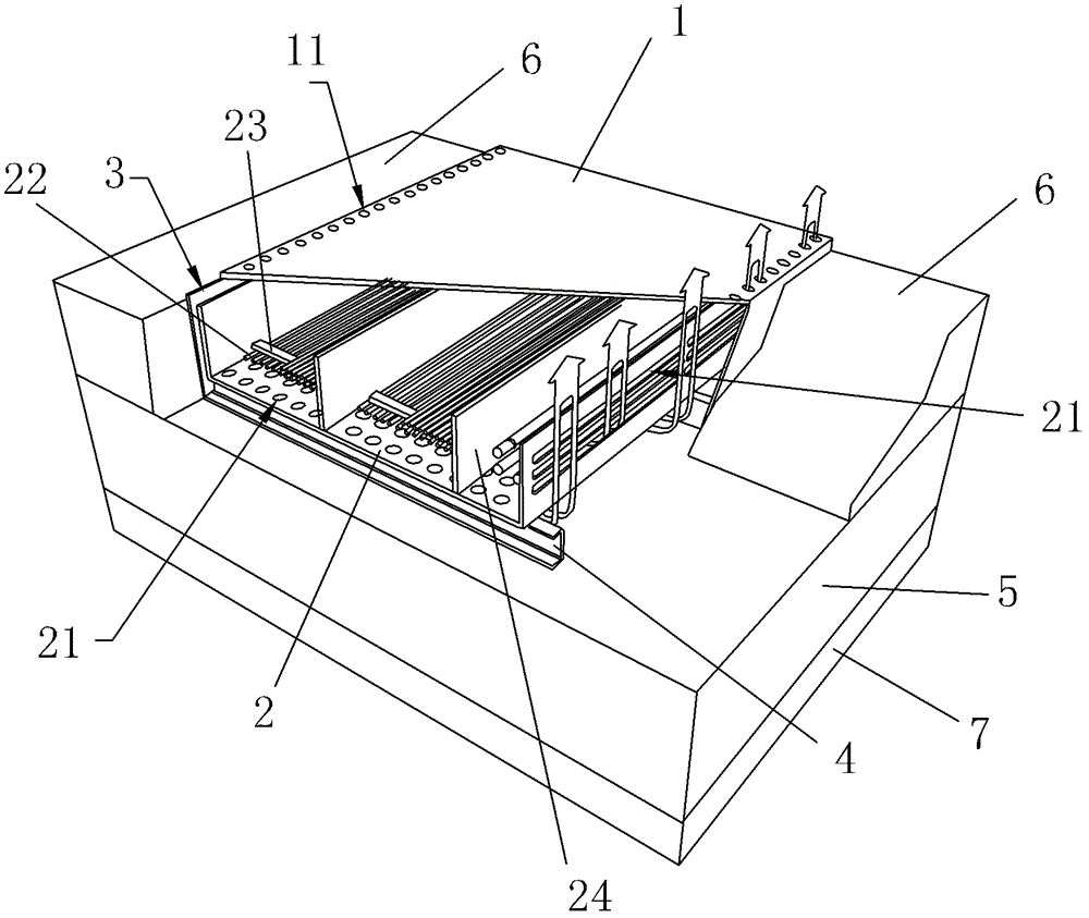
[0021] Embodiment 1: Assembled cable trench body in substation, such as figure 1 As shown, it consists of a series of U-shaped waterproof ditch bodies connected in turn. Each U-shaped ditch body 1 is provided with a U-shaped moisture-proof support body 2 in the inner cavity, U-shaped ditch body 1 and U-shaped ditch body. The moisture-proof support bodies 2 are snapped together in opposite directions, and the middle part forms a cable laying channel. The front and rear ends of the U-shaped waterproof ditch body are respectively provided with a flange section and a concave joint groove that can be connected back and forth to form a front and rear lap joint groove, and double P rubber strips are installed between the front and back ditch bodies. The U-shaped ditch body 1 and the U-shaped moisture-proof support body 2 are made of C30-C40 reinforced concrete or steel fiber concrete (appearance grade of fair-faced concrete).

[0022] In order to make reasonable use of the space, th...


PUM


Abstract

The invention relates to a transformer substation assembled type cable groove body and a cable channel system thereof. The transformer substation assembled type cable groove body is formed by connecting waterproof groove bodies with a U-shaped cross section in sequence, and is characterized in that: a U-shaped moisture-proof supporting body is arranged in an inner cavity of each U-shaped groove body; and the U-shaped groove bodies are oppositely buckled with the U-shaped moisture-proof supporting bodies, and a cable paving channel is formed between the U-shaped groove bodies and the U-shaped moisture-proof supporting bodies. The cable channel system applying the transformer substation assembled type cable groove body comprises a base body, wherein the transformer substation assembled type cable groove body is arranged on the base body; and the base body comprises a soil filled layer and a water filtering layer arranged on the soil filled layer. The transformer substation assembled type cable groove body and the cable channel system using the same, provided by the invention, have the outstanding substantive characteristics as follows: the U-shaped groove bodies are oppositely buckled with the U-shaped moisture-proof supporting bodies, so that the cable paving channel has moisture-proof and waterproof effects; and supporting rods, moisture-proof separating bars, top air vents or ventilating grooves, middle air vents or ventilating grooves and the like are arranged, so that water, such as water vapor in the cable paving channel, can be discharged in time.

Description

technical field [0001] The invention relates to a substation cable laying system, in particular to a substation assembled cable trench body and a cable passage system thereof. Background technique [0002] At present, the design of cable trenches for substations above 220kV is made of brick, plain concrete, and reinforced concrete cable trenches according to the embedding depth, load size, and groundwater level, which can meet the cable laying requirements of substations and power plants. However, with the development of my country's electric power industry, this kind of on-site cable trench also faces the following problems: [0003] 1. The amount of on-site masonry work is large and the construction time is long: taking a 220kV substation as an example, it is converted into a 1.1x0.85m cable trench, and its total length is about 1100m. The estimated cost of brick cable trench is 625 yuan / m 3 According to the space inside the ditch, the same below, the construction period...

Claims


Application Information

Patent Timeline
Patent Type & Authority Patents(China)
IPC IPC(8): H02G9/02
Inventor 郭云鹏江学斌毛建伟吴亮况骄庭梁樑俞哲人梁伟芬方靖宇张金强吕明周全汪宏华吕浩华杜青
Owner 国网浙江省电力公司电动汽车服务分公司
Why Eureka
Try Eureka