

Z-axis servomotor integrated with power-off braking device
A technology of servo motors and braking devices, which is applied in the direction of electromechanical devices, electric components, and control of mechanical energy. It can solve the problems of insufficient response and insufficient braking torque, achieve shortened response time, large braking torque, and prevent accidents. The effect of the accident
- Summary
- Abstract
- Description
- Claims
- Application Information
AI Technical Summary
Problems solved by technology
Method used
Image

Examples
specific Embodiment approach 1
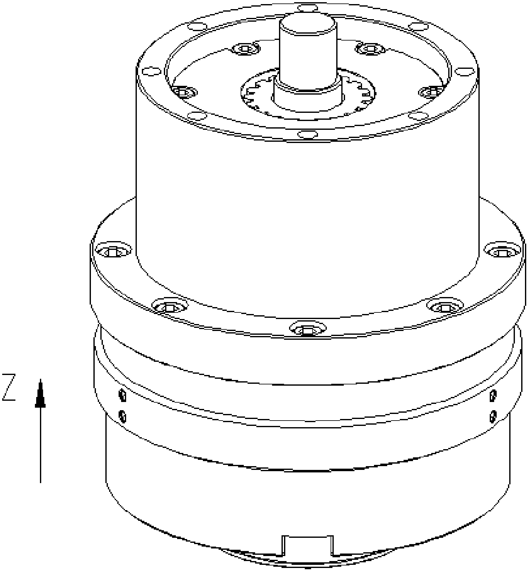
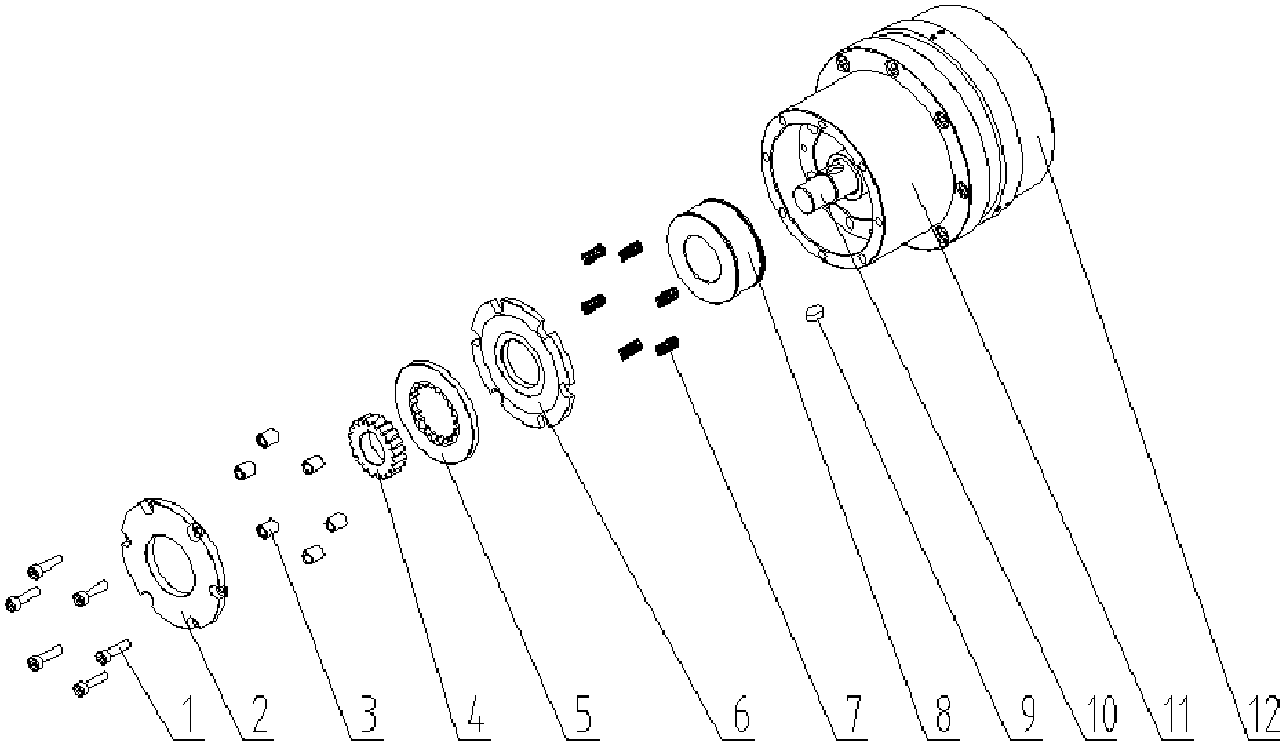
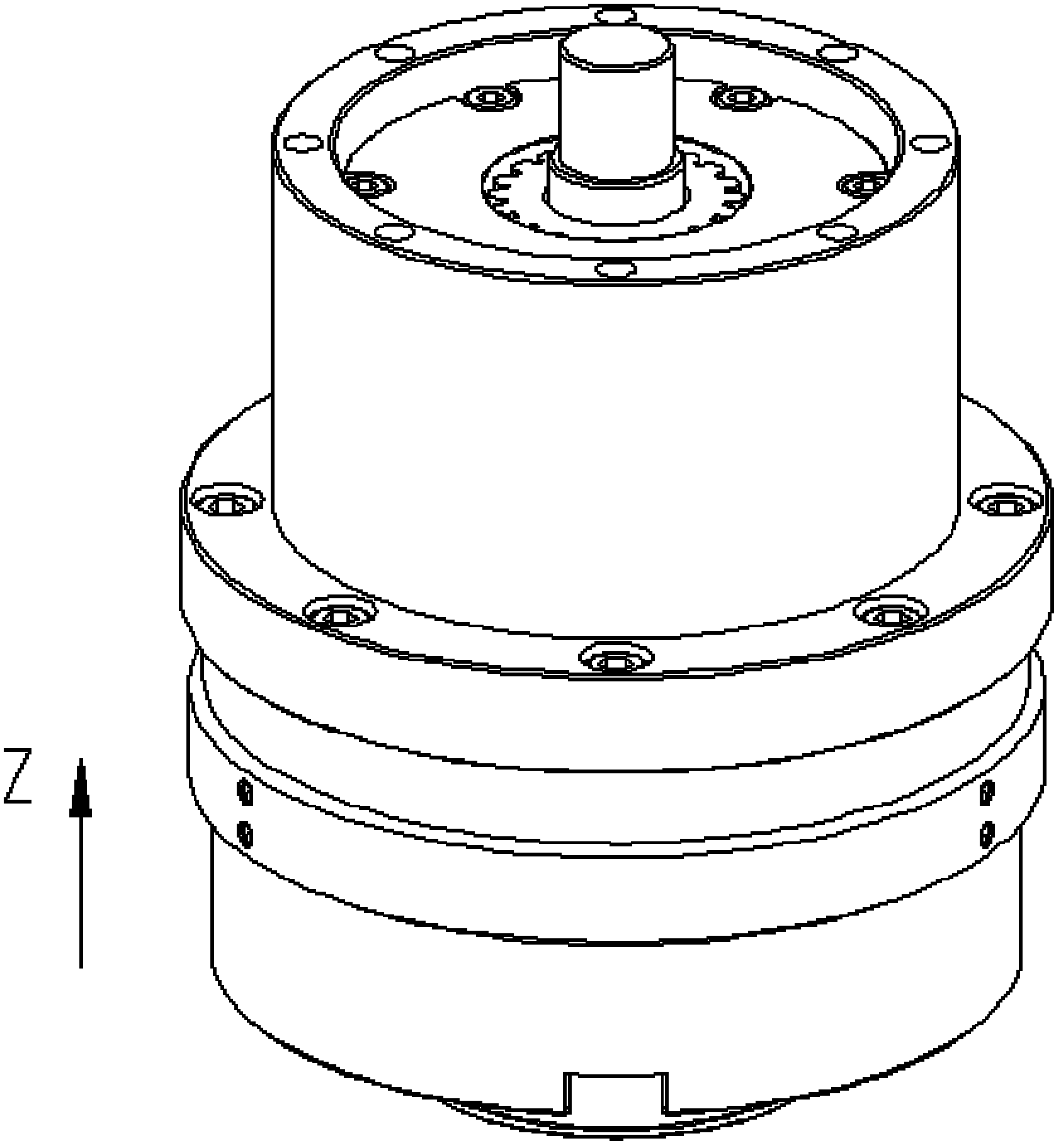
[0011] DETAILED DESCRIPTION OF THE PREFERRED EMBODIMENTS 1. A Z-axis servo motor integrated with a power-off braking device, which is composed of a Z-axis servo motor 12 and a power-off braking device, and the power-off braking device is fixed at the output of the Z-axis servo motor 12 On the end face of one side of the shaft, the power-off braking device includes an annular side wall 11, a fixed friction plate 2, a distance positioning sleeve 3, a tooth cog 4, a tooth insert friction plate 5, a movable friction plate 6, an elastic device 7 and solenoid coil 8,
[0012] The annular side wall 11 is fixed on the end cover of the Z-axis servo motor 12, and the annular side wall 11 is coaxial with the output shaft of the Z-axis servo motor 12;
[0013] The electromagnet coil 8 is set on the outside of the Z-axis motor shaft 10 of the Z-axis servo motor 12, and is fixedly connected with the end cover of the Z-axis servo motor 12, and there is a gap between the inner wall of the ele...
specific Embodiment approach 2
[0019] Embodiment 2. The difference between this embodiment and Embodiment 1 is that this embodiment is a further limitation of Embodiment 1, and the elastic device 7 is realized by a spring.
specific Embodiment approach 3
[0020] Embodiment 3. The difference between this embodiment and Embodiment 1 is that this embodiment is a further limitation of Embodiment 1. The elastic device 7 is realized by a spring, which is sleeved on the Z-axis motor shaft 10 .
PUM
 Abstract
Description
Claims
Application Information