Receiver

A receiver and coupling technology, applied in frequency demodulator layout, angle demodulation through phase difference detection, digital transmission system, etc., can solve the problem of increasing the volume of the receiver 100

Inactive Publication Date: 2012-07-18
林宗贤
View PDF4 Cites 3 Cited by
  • Summary
  • Abstract
  • Description
  • Claims
  • Application Information

AI Technical Summary

Problems solved by technology

In this way, the volume of the receiver 100 will be increased

Method used


Image

  • Receiver
  • Receiver
  • Receiver

Examples


Embodiment Construction

[0020] In order to further illustrate the technical means and effects of the present invention to achieve the intended purpose of the invention, the specific implementation, methods, steps, structures, features and characteristics of the receiver proposed in accordance with the present invention will be described below with reference to the drawings and preferred embodiments. Efficacy, as detailed below.

[0021] The foregoing and other technical content, features and effects of the present invention will be clearly presented in the following detailed description of the preferred embodiments with reference to the drawings. Through the description of the specific embodiments, a more in-depth and specific understanding of the technical means and effects adopted by the present invention to achieve the predetermined purpose can be obtained. However, the accompanying drawings are only for reference and explanation, and are not used to limit the present invention. .

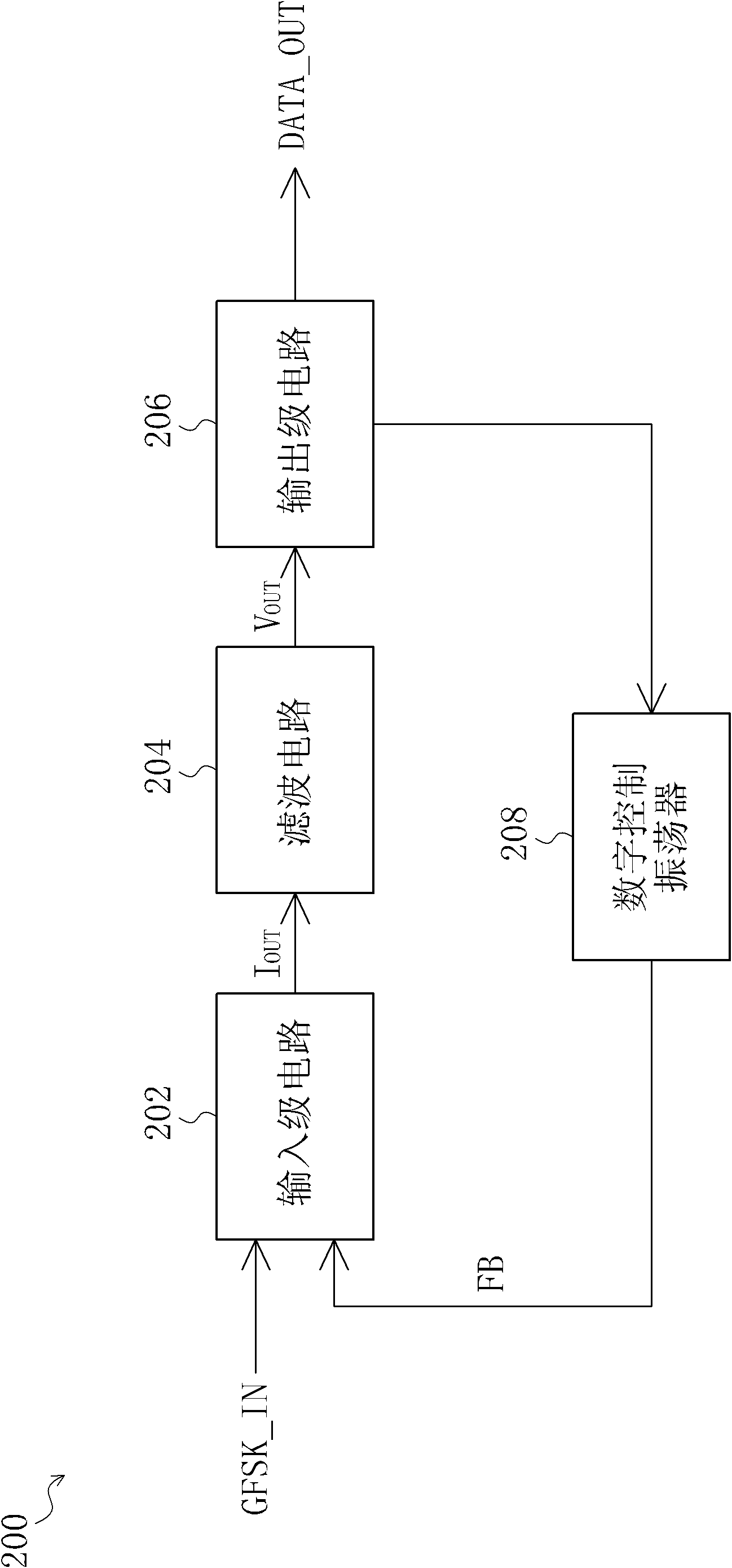
[0022] figure 2 I...


PUM


Abstract

A receiver comprises an input-stage circuit, a filter circuit, an output-stage circuit and a digital control oscillator. The input-stage circuit has a mixer configured for mixing the GFSK signal and a feedback signal to generate an input-stage current signal to the filter circuit. Then the filter circuit filters the input-stage current signal, and converts it into a voltage signal. The output-stage circuit is coupled to the filter circuit, for converting the voltage signal into a digital output data. In addition, the digital control oscillator is coupled to the output-stage circuit, for outputting the feedback signal based on the digital output data.

Description

Technical field [0001] The present invention relates to a receiver, in particular to a receiver for receiving Gaussian phase shift key (hereinafter referred to as GFSK) signals. Background technique [0002] figure 1 It is the system block diagram of the existing GFSK receiver. Please refer to figure 1 The existing GFSK receiver 100 includes a phase frequency detector (PFD) 102, a charge pump 104, a filter 106, a thermometer code generator 108, an analog-to-digital converter (DAC) 110, and a voltage-controlled oscillator 器(VCO) 112. The phase frequency detector 102 will receive the GFSK signal GFSK_IN and compare it with the feedback signal FB to generate a comparison result. The comparison result is sent to the charge pump 104 to generate the voltage signal V1. Then, the filter 106 filters the voltage signal V1 to eliminate noise, and sends the filtered voltage signal V1' to the thermometer code generator 108. Thereby, the thermometer code generator 108 can generate the digit...

Claims


Application Information

Patent Timeline
Patent Type & Authority Applications(China)
IPC IPC(8): H04L27/14
CPCH04L2027/0028H04L27/2272H03D3/06H03D3/004H04L2027/0059H04L2027/0069
Inventor 刘慧贤林宗贤刘耀鸿
Owner 林宗贤
Why Eureka
Try Eureka