Two-edge special end milling cutter for through groove

A technology for end mills and through grooves, which is applied in the direction of milling cutters, milling machine equipment, manufacturing tools, etc. It can solve the problems of edge chipping, uneven groove bottom, and difficult chip removal, etc., and achieves sharp end cutting edges, good surface quality, The effect of high cutting efficiency

Inactive Publication Date: 2012-07-25
合肥波林新材料股份有限公司
View PDF9 Cites 2 Cited by
  • Summary
  • Abstract
  • Description
  • Claims
  • Application Information

AI Technical Summary

Problems solved by technology

Ordinary two-edged flat-end milling cutter, its end face cutting edge is a straight cutting edge on the spiral groove, the cutting edge is not sharp and has a large contact surface with the workpiece during cutting, and chip removal is difficult, so the milled groove bottom is often not Flat, with obvious knife lines, and often chipping and broken knives

Method used


Image

  • Two-edge special end milling cutter for through groove
  • Two-edge special end milling cutter for through groove
  • Two-edge special end milling cutter for through groove

Examples


Embodiment 1

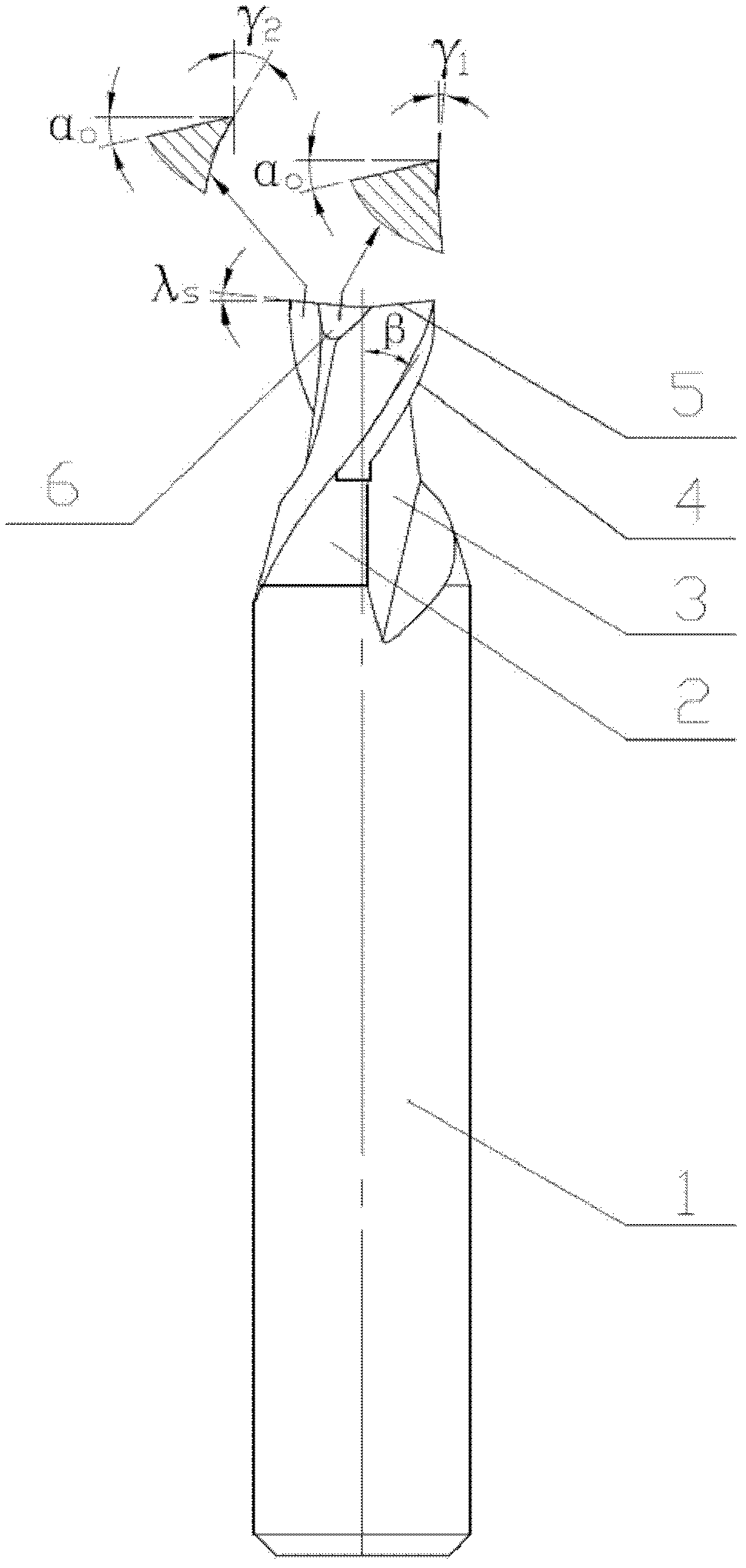
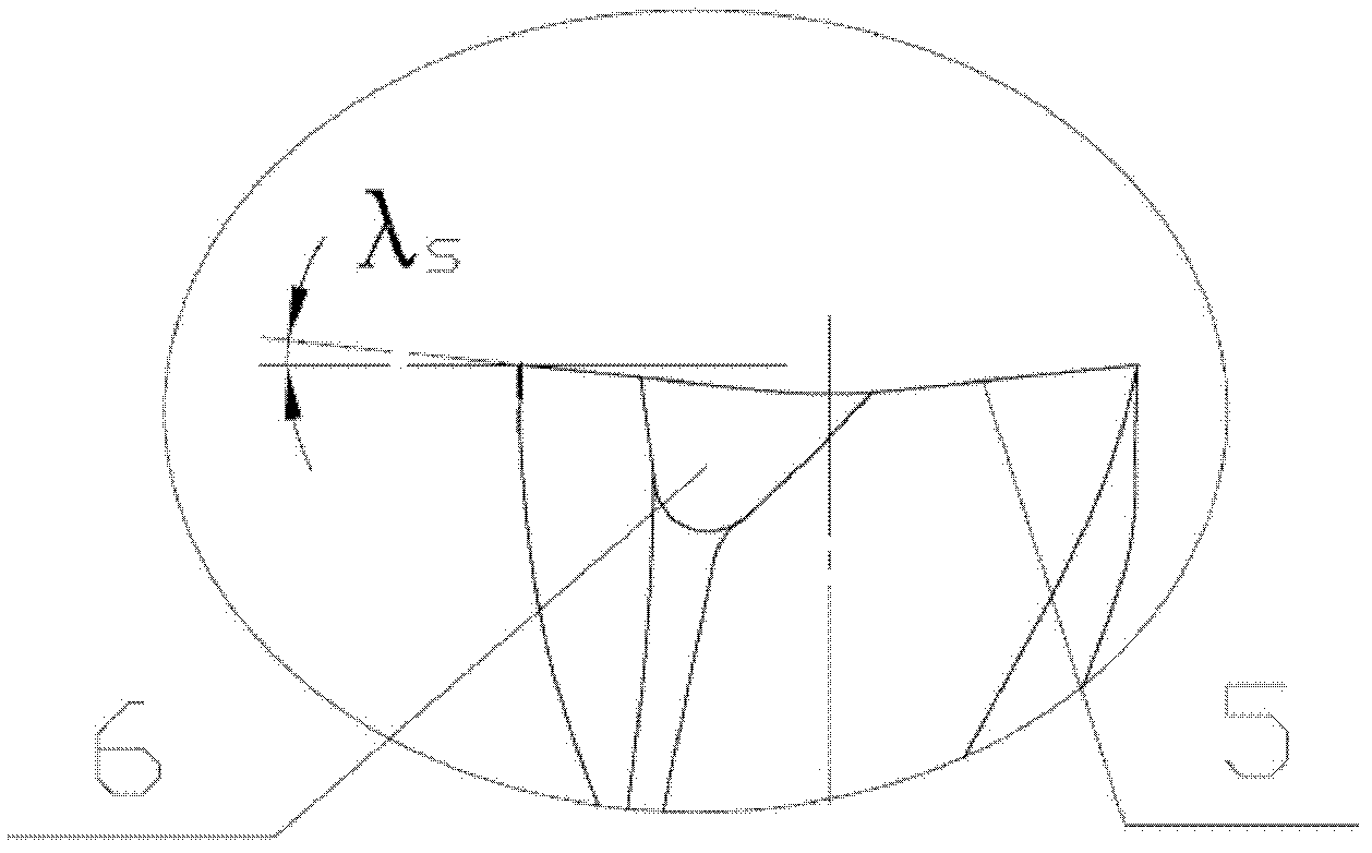
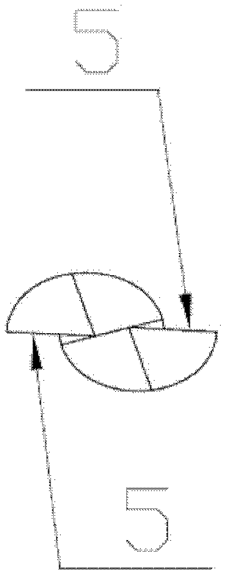
[0018] like Figure 1a , Figure 1b and Figure 1c As shown, the present embodiment is a two-edged through-groove special end mill, which processes the through-groove 7 on the workpiece 8 . The special end mill for two-edge through-groove includes a tool handle 1 and a cutter body 2. The cutter body 2 is composed of a spiral groove 3, a side edge 4, an end face cutting edge 5 and a chip removal groove 6. The end face cutting edge 5 is set on the cutter body 2. The top end, the inclination angle λ of the end face cutting edge 5 s = 3°; the chip removal groove 6 is set on the spiral groove 3 close to the center of the end face cutting edge 5, and the rake angle γ inside the end face cutting edge 5 1 = 0°, the rake angle γ on the outer side of the end face cutting edge 5 2 = 30°, clearance angle α of end face cutting edge 5 0 =12°, the helix angle β of the spiral groove 3=30°.

[0019] There are two end face cutting edges 5, which are arranged symmetrically on the top of the...

Embodiment 2

[0023] The difference between this embodiment and Embodiment 1 is that the inclination angle λ of the end face cutting edge 5 s =8°; the rake angle γ of the inner side of the end face cutting edge 5 1 = 10°, the relief angle α of the end face cutting edge 5 0 = 15°.

[0024] The inclination angle of the end face cutting edge 5 is given by λ s = 3° change to λ s =8°; the cutting edge becomes sharper, and the processed groove bottom is flat, but the strength of the cutting edge is weakened. The rake angle on the inner side of the end face cutting edge 5 is determined by γ 1 = 0° changes to γ 1 =10°, the relief angle of the end face cutting edge 5 is determined by α 0 = 12° changed to α 0 =15°, making the cutting edge become sharper, but the strength is weakened.

Embodiment 3

[0026] The difference between this embodiment and Embodiment 1 is that the inclination angle λ of the end face cutting edge 5 s = 5°; the rake angle γ inside the end face cutting edge 5 1 = 5°, the relief angle α of the end face cutting edge 5 0 = 13°.

[0027] Compared with the end mills of Embodiment 1 and Embodiment 2, the end mills using this set of data have better cutting performance and service life.


PUM


Abstract

The invention discloses a two-edge special end milling cutter for a through groove, which comprises a cutter handle and a cutter body. The cutter body consists of a spiral groove, a side edge, an end surface cutting edge and a chip discharge groove. The two-edge special end milling cutter is characterized in that the end surface cutting edge is arranged at the top end of the cutter body and the inclination angle lambda s is equal to 3-8 degrees; and the chip discharge groove is arranged on the spiral groove adjacent to the central part of the end surface cutting edge, the front angle gamma 1 of the internal side of the end surface cutting edge is equal to 0-10 degrees, the front angle gamma 2 of the external side of the end surface cutting edge is equal to 30 degrees, the rear angle alpha 0 of the end surface cutting edge is equal to 12-15 degrees and the spiral angle beta of the spiral groove is equal to 30 degrees. The end milling cutter has the advantages that the cutting edge is sharp, the chips are discharged smoothly, the processing efficiency is high, the problems that the groove bottom quality is poor and the cutter is apt to be broken when the common two-edge end milling cutter is used for milling through grooves are solved, and the end milling cutter is suitable for processing all kinds of through grooves.

Description

technical field [0001] The invention relates to an end mill, which belongs to the technical field of tool manufacturing in the machining industry, in particular to a special end mill for two-edged through-groove. Background technique [0002] Milling slots is usually done with end mills. Ordinary two-edged flat-end milling cutter, its end face cutting edge is a straight cutting edge on the spiral groove, the cutting edge is not sharp and has a large contact surface with the workpiece during cutting, and chip removal is difficult, so the milled groove bottom is often not Flat, with obvious knife lines, and often chipping and broken knives. In order to overcome the shortcomings of existing products, it is of practical significance to develop a two-edged end mill suitable for through-slot milling. Contents of the invention [0003] The object of the present invention is to provide a two-edged through-groove special end mill that is not easy to chip and break, has high cutti...

Claims


Application Information

Patent Timeline
Patent Type & Authority Applications(China)
IPC IPC(8): B23C5/10
Inventor 沈军徐伟任刚强
Owner 合肥波林新材料股份有限公司
Why Eureka
Try Eureka