Milling cutter

A technology of milling tools and cutting blades, which is applied in the direction of milling cutters, manufacturing tools, milling machine equipment, etc., can solve the problems of the limited number of milling tool edges, large cutting force of milling tools, and large wrench movable space, so as to reduce cutting force and prolong Longevity and effect of cutting vibration reduction

Inactive Publication Date: 2012-07-25
ZHUZHOU CEMENTED CARBIDE CUTTING TOOLS CO LTD
View PDF8 Cites 5 Cited by
  • Summary
  • Abstract
  • Description
  • Claims
  • Application Information

AI Technical Summary

Problems solved by technology

But, because the center hole of cutting blade is positioned at the center position of blade, and the head of wrench inserts fastening recess and needs larger wrench movable space when fastener is operated, this just has to be set larger on cutter body. Avoid space, the number of edges of milling tools is greatly limited, and the cutting efficiency is low
In addition, with the same efficiency, milling tools with fewer edges have higher cutting force and are prone to vibration

Method used


Image

  • Milling cutter
  • Milling cutter
  • Milling cutter

Examples


Embodiment Construction

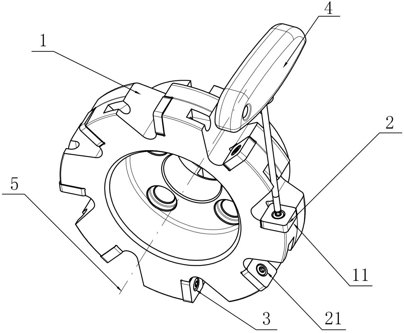
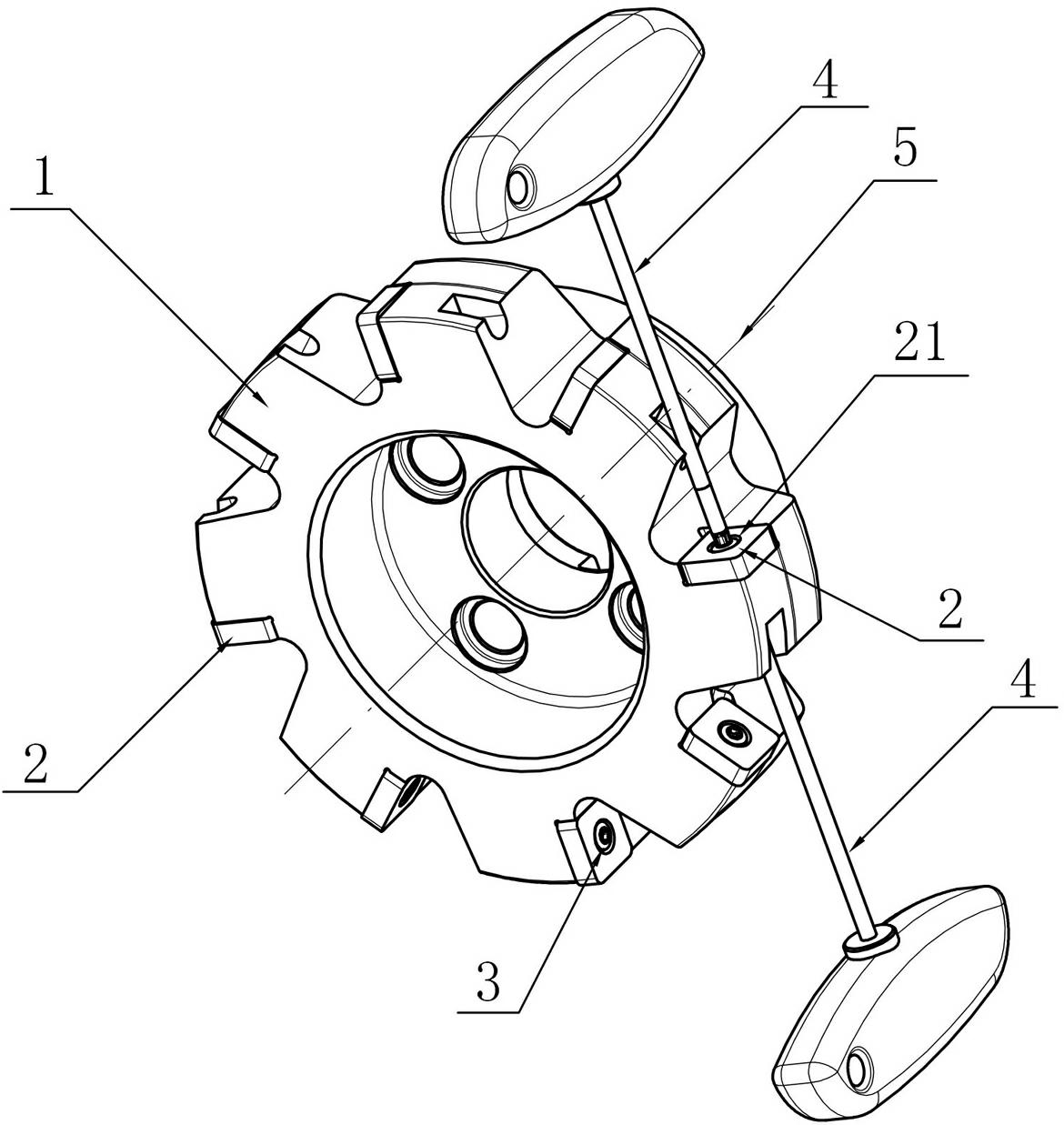
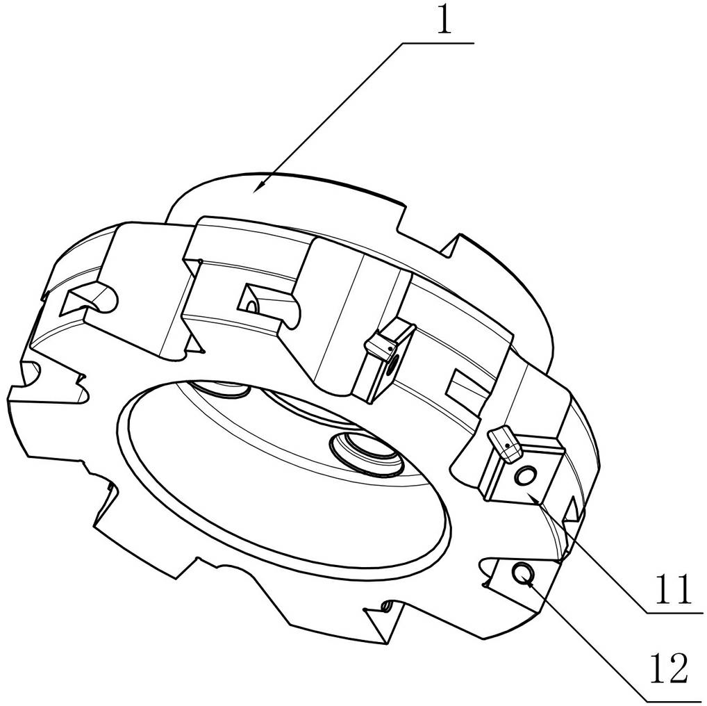
[0020] Figure 2 to Figure 5 An embodiment of a milling tool according to the present invention is shown. The milling tool rotates around an axis 5 during operation. It includes a cutter body 1, a cutting blade 2 and a fastener 3. At least one set of sipe grooves 11 is provided on the cutter body 1. A cutting blade 2 is installed in each sipe 11, the cutting blade 2 is provided with a central hole 21, the bottom surface of the sipe 11 is provided with a fastener connecting hole 12, and the head 31 of the fastener 3 is pressed in the central hole 21 Inside, the tail 32 of the fastener 3 passes through the central hole 21 and is connected to the fastener connection hole 12, and the tail end of the fastener 3 is provided with a first recessed hole 33 for plugging in with the wrench 4, and the fastener is connected The hole 12 runs through the cutter body 1, so that the wrench 4 can be inserted from the tail end of the fastener 3, and the fastener 3 is tightened so that the wrench...


PUM


Abstract

The invention discloses a milling cutter, comprising a cutter body, cutting blades and a fastening piece, wherein the cutter body is at least provided with a group of cutter grooves; each cutter groove is internally provided with one cutting blade; each cutting blade is provided with a central hole and fastening piece connecting holes are arranged in the bottom surfaces of the cutter grooves; the head part of the fastening piece is pressed into the central hole and the tail part of the fastening piece passes through the central hole to be connected with the fastening piece connecting holes; the tail end of the fastening piece is provided with a first concave hole which is connected with a wrench in an inserting manner; and the fastening piece connecting holes pass through the cutter body. The milling cutter disclosed by the invention has the advantages of simple structure, convenience for attaching and detaching, relatively-increased blade number, high cutting efficiency, small cutting force and small vibration.

Description

technical field [0001] The present invention relates to cutting tools for metalworking, and more particularly to milling tools. Background technique [0002] In the milling process, the milling tool with the structure that the fastener clamps the cutting blade in the groove through the hole of the cutting blade is simple in structure, easy to assemble and disassemble, and can provide a large clamping force for the cutting blade, so that the milling tool has a relatively Strong impact resistance and long service life, so this tool structure is widely used in milling tools. [0003] Such milling tools are generally used as figure 1 The shown structure rotates around the central axis 5 during its work. It is mainly composed of a cutter body 1, a cutting blade 2 and a fastener 3. The cutter body 1 is provided with at least one set of sipes 11 and fastener mounting holes for cutting The blade 2 is placed in the sipe 11, the fastener 3 passes through the central hole 21 of the c...

Claims


Application Information

Patent Timeline
Patent Type & Authority Applications(China)
IPC IPC(8): B23C5/20B23C5/22
Inventor 江爱胜易为
Owner ZHUZHOU CEMENTED CARBIDE CUTTING TOOLS CO LTD
Why Eureka
Try Eureka