Crystalline silicon single-knife guillotine

A cutting machine, crystal silicon technology, applied in the direction of manufacturing tools, stone processing equipment, work accessories, etc., can solve the problems of silicon rod transfer difficulties, not considering the silicon rod crystal pulling process, overcapacity, etc., to improve cutting stability , compact structure, and the effect of reducing equipment manufacturing costs

Pending Publication Date: 2018-11-06
QINGDAO GAOCE TECH CO LTD
View PDF0 Cites 5 Cited by
  • Summary
  • Abstract
  • Description
  • Claims
  • Application Information

AI Technical Summary

Problems solved by technology

With the improvement of the crystal pulling process, the length of the silicon rods smelted by the crystal pulling furnace is lengthened, but the applicable rod length range of the multi-knife cutting machine on the market has not reached the new rod length. At the same time, a large number of crystal silicon factories are under construction. At that time, it did not consider that there would be a breakthrough in the silicon ingot pulling process, and it was developing towards longer and longer lengths, which made it difficult to transfer silicon ingots in the factory.
In addition, for small and medium-sized enterprises, in order to ensure the continuity of operations and production capacity, two sets of equipment are generally arranged to operate continuously and alternately, and there is a phenomenon of overcapacity

Method used


Image

  • Crystalline silicon single-knife guillotine
  • Crystalline silicon single-knife guillotine
  • Crystalline silicon single-knife guillotine

Examples


Embodiment 1

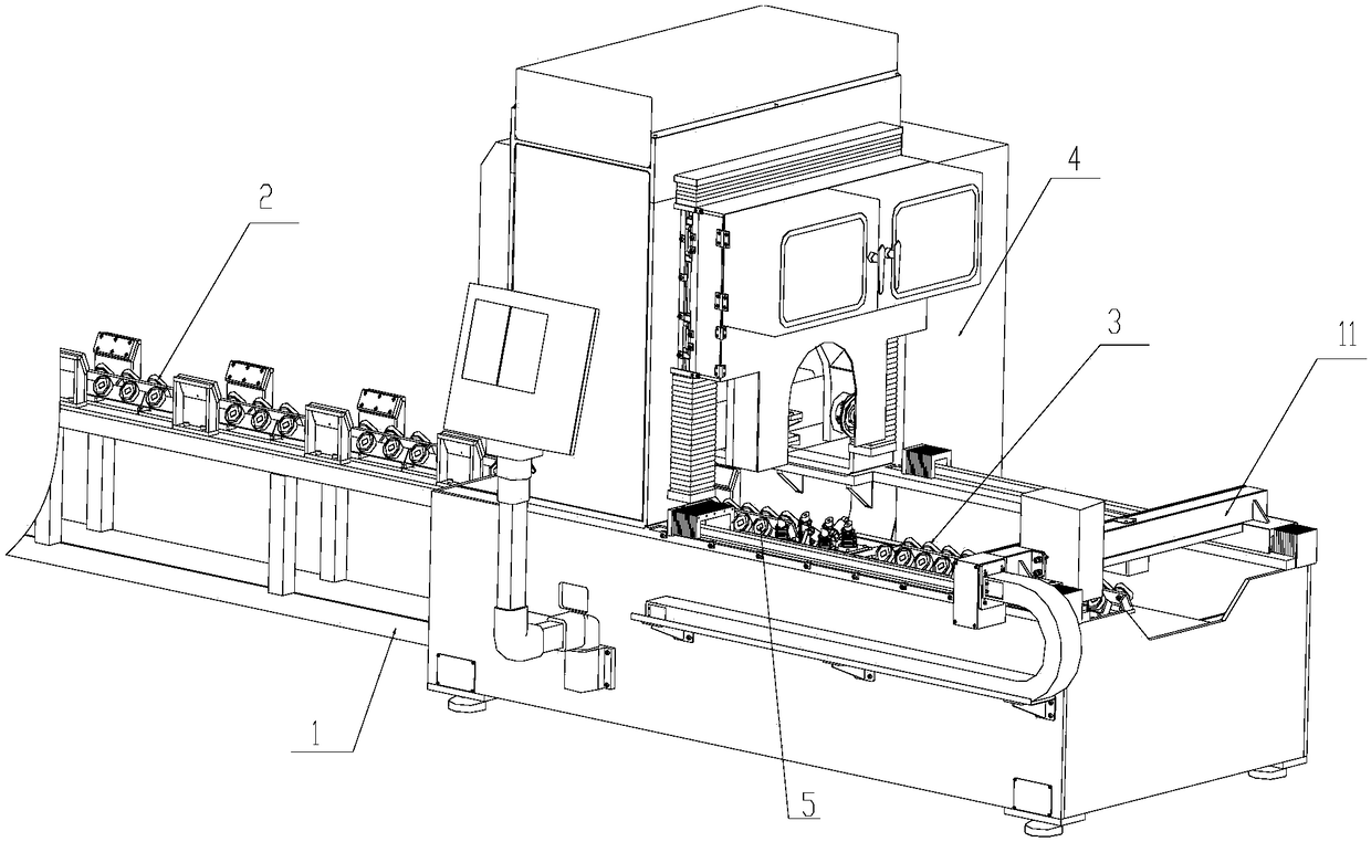
[0029] refer to figure 1 , a crystal silicon single-knife cutting machine, including a base 1, a conveying mechanism and a cutting mechanism 4, the conveying mechanism and the cutting mechanism 4 are located above the base 1. The conveying mechanism is divided into two stages along the axial direction of the crystal silicon, which are respectively the feed conveying assembly 2 and the unloading conveying assembly 3. The crystal silicon is conveyed to the cutting mechanism 4 through the feed conveying assembly 2 for cutting. The crystalline silicon is exported through the feeding and conveying assembly 3.

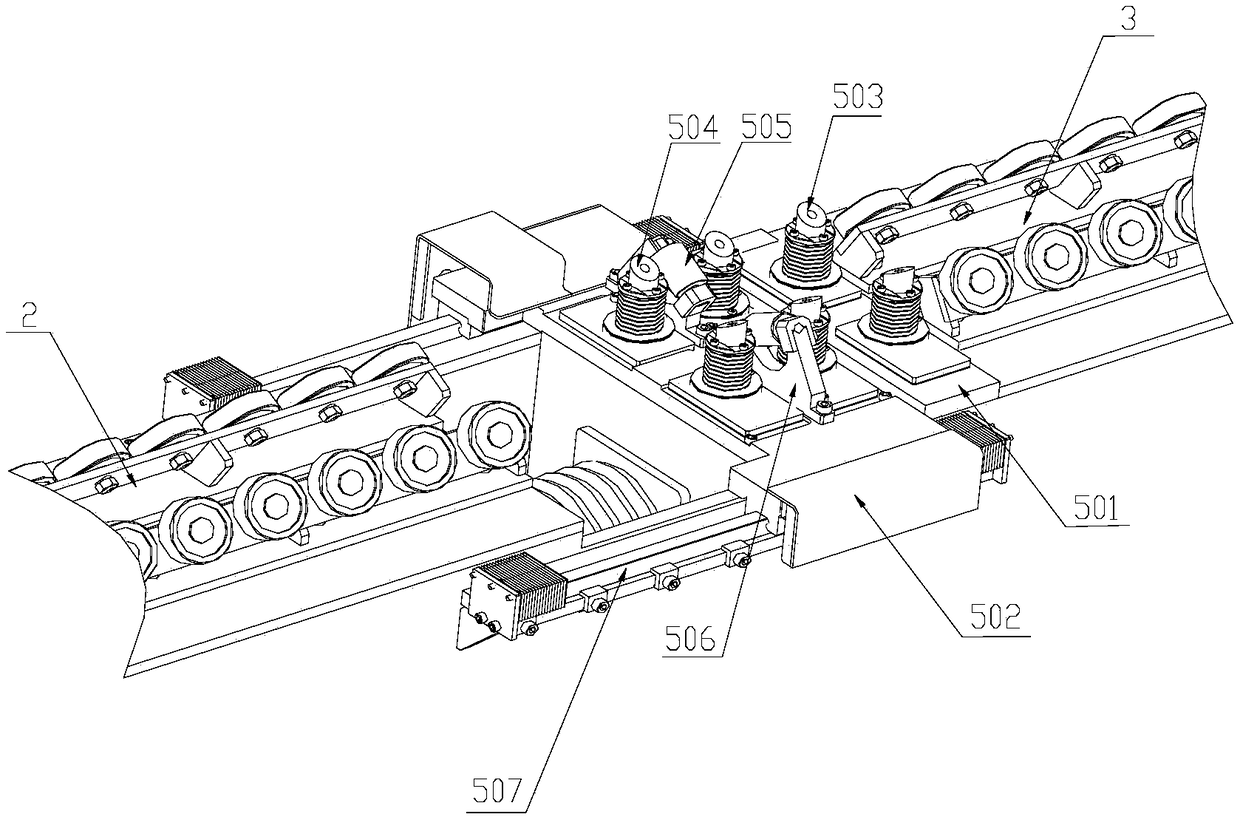
[0030] In order to facilitate the cutting of crystal silicon of different lengths, a movable supporting mechanism 5 is provided between the feeding conveying assembly 2 and the unloading conveying assembly 3 . refer to figure 2 , the movable support mechanism 5 includes a relatively slidable first slide table 501 and a second slide table 502, the base 1 is provided with a...

Embodiment 2

[0034] refer to figure 1 , Figure 4 with Figure 5 , the cutting mechanism 4 straddles above the movable supporting mechanism 5 and is connected to the base 1 through a supporting column 6 . The cutting mechanism 4 includes a support frame 401, a lift assembly 402 and a cutting head, wherein the lift assembly 402 is fixedly connected to the support column 6, the cutting head is located on the support frame 401, and at the same time, the lift assembly 402 passes through the connecting plate 7 It is connected with the support frame 401 to push the support frame 401 to slide along the support column 6 , and the support frame 401 is provided with a through hole 403 through which the crystal silicon passes. When the crystalline silicon is located in the through hole 403 , the lifting assembly 402 drives the cutting head to move down to cut the crystalline silicon.

[0035]The lift assembly 402 includes a lift motor 412, a reducer 413 and a first ball screw 414, the output end o...

Embodiment 3

[0040] refer to figure 1 with Image 6 , the jaw assembly 11 is provided at the blanking and conveying assembly 3, and the jaw assembly 11 includes a beam 1101 and a drive motor 1102. The beam 1101 is perpendicular to the axial direction of the crystal silicon, and it is close to the One side is provided with a positioning block 1103 communicating with the beam 1101 , and the driving motor 1102 is located on the other side of the beam 1101 . The base 1 is provided with a feed slide rail extending along the axial direction of the crystal silicon, and the driving motor 1102 drives the jaw assembly 11 to move along the feed slide rail to drag the crystal silicon to be transported along the conveying mechanism.

[0041] The end of the positioning block 1103 is provided with a vacuum chuck 1104, and the vacuum chuck 1104 is used to suck the crystal silicon or the sample that needs to be cut. At the same time, the positioning block 1103 can effectively prevent the crystal silicon o...


PUM


Abstract

The invention relates to a crystalline silicon single-knife guillotine, and belongs to the technical field of crystalline silicon processing equipment. The crystalline silicon single-knife guillotineincludes a base, a conveying mechanism and a cutting mechanism, wherein the conveying mechanism and the cutting mechanism are located above the base; the conveying mechanism is divided into two levelsin the axial direction of the crystalline silicon, the two levels are the feeding conveying assembly and the discharging conveying assembly respectively, a moving supporting mechanism is arranged between the feeding conveying assembly and the discharging conveying assembly, and the cutting mechanism is arranged above the moving supporting mechanism in a cross mode; and a clamping claw assembly isarranged on the discharging conveying assembly. According to the crystalline silicon single-knife guillotine, the conveying mechanism is combined with the moving supporting mechanism so as to fix thecrystalline silicon with different cutting lengths, and the flexibility is high; and meanwhile, the integration of winding, rewinding and cutting functions is achieved, the structure is compact, theequipment manufacturing cost is reduced, the crystalline silicon single-knife guillotine is also adapt to factory layout needs, the structure is compact, the economy and durability are achieved, and the application prospects are wide.

Description

technical field [0001] The invention belongs to the technical field of crystal silicon processing equipment, in particular to a crystal silicon single-knife cutting machine. Background technique [0002] The manufacturing process of silicon wafers used in making solar panels is divided into several steps: crystal pulling, truncation, squaring, grinding, and slicing. At present, the wire cutting technology is a relatively advanced crystal silicon cutting processing technology. Its principle is to rub the crystal silicon through a high-speed moving cutting wire to achieve the purpose of cutting. [0003] The multi-knife cutting machine is the most widely used. It uses the guide wheel to arrange the cutting wire into a net shape, and can complete the multi-knife cutting of crystal silicon through one-time operation from top to bottom. With the improvement of the crystal pulling process, the length of the silicon rods smelted by the crystal pulling furnace is lengthened, but th...

Claims


Application Information

Patent Timeline
Patent Type & Authority Applications(China)
IPC IPC(8): B28D5/04B28D7/00B28D7/04
CPCB28D5/045B28D5/0058B28D5/0082B28D5/0094
Inventor 段景波王鹏解培玉
Owner QINGDAO GAOCE TECH CO LTD
Why Eureka
Try Eureka