Vertical cutting device for tubular workpiece

A cutting device and workpiece technology, applied in the direction of pipe shearing device, shearing device, accessory device of shearing machine, etc., can solve the problems of low incision quality and poor workpiece cutting stability, so as to ensure the incision quality, improve the cutting efficiency, The effect of improving cutting stability

Inactive Publication Date: 2019-08-27
赵言
View PDF10 Cites 5 Cited by
  • Summary
  • Abstract
  • Description
  • Claims
  • Application Information

AI Technical Summary

Problems solved by technology

[0003] For the cutting of tubular workpieces, the traditional cutting machine adopts a semi-automatic method. It is necessary to manually fix the tube to hold the workpiece and push the cutting wheel to move, resulting in poor cutting stability of the workpiece and poor incision quality.

Method used


Image

  • Vertical cutting device for tubular workpiece
  • Vertical cutting device for tubular workpiece
  • Vertical cutting device for tubular workpiece

Examples


Embodiment 1

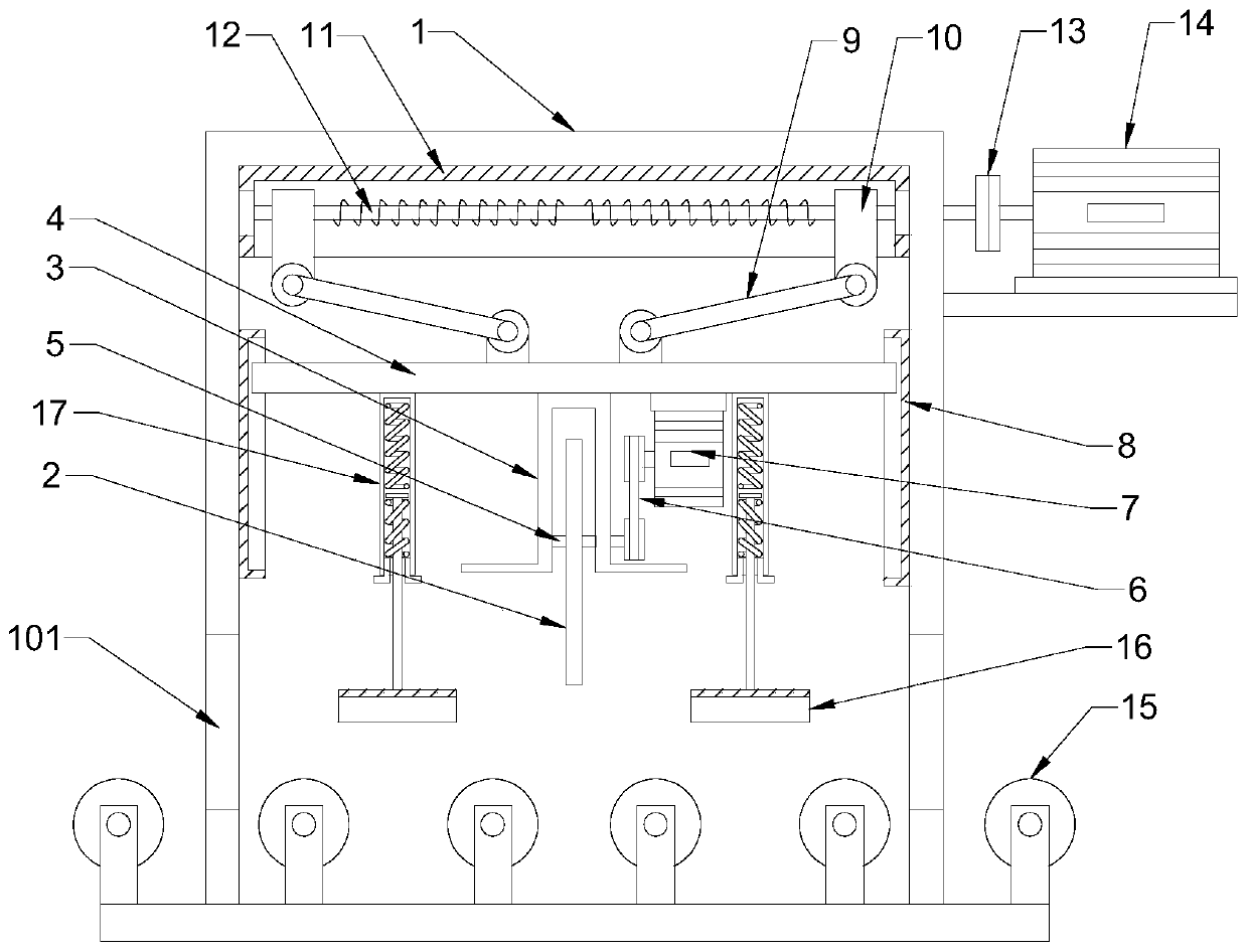
[0021] see Figure 1-3 , in an embodiment of the present invention, a vertical cutting device for a tubular workpiece includes a cutting box 1, a cutting wheel 2 and a conveying roller 15; the cutting box 1 is a hollow box with opposite through holes 101 arranged on both sides, The through hole 101 is for the steel pipe to enter the cutting box 1; the bottom plate of the cutting box 1 is provided with conveying rollers 15 distributed equidistantly, and the conveying roller 15 is connected with a driving device to realize the feeding of the steel pipe; the cutting wheel 2 is connected by rotating shaft 5 There is a protective cover 3, and the protective cover 3 avoids cutting sparks from splashing; the upper end of the protective cover 3 is fixedly connected with a lifting plate 4, and the rotating shaft 5 extends to the outside of the protective cover 3 and is connected to the output shaft of the cutting motor 7 through the transmission belt 6, and the cutting motor 7 is fixed...

Embodiment 2

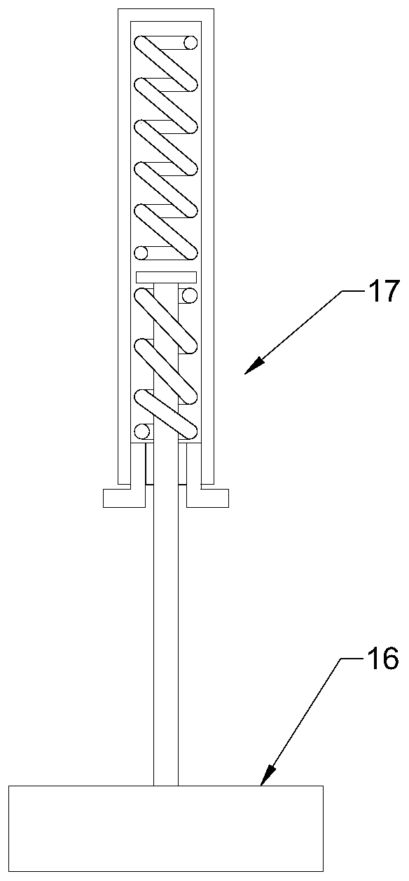
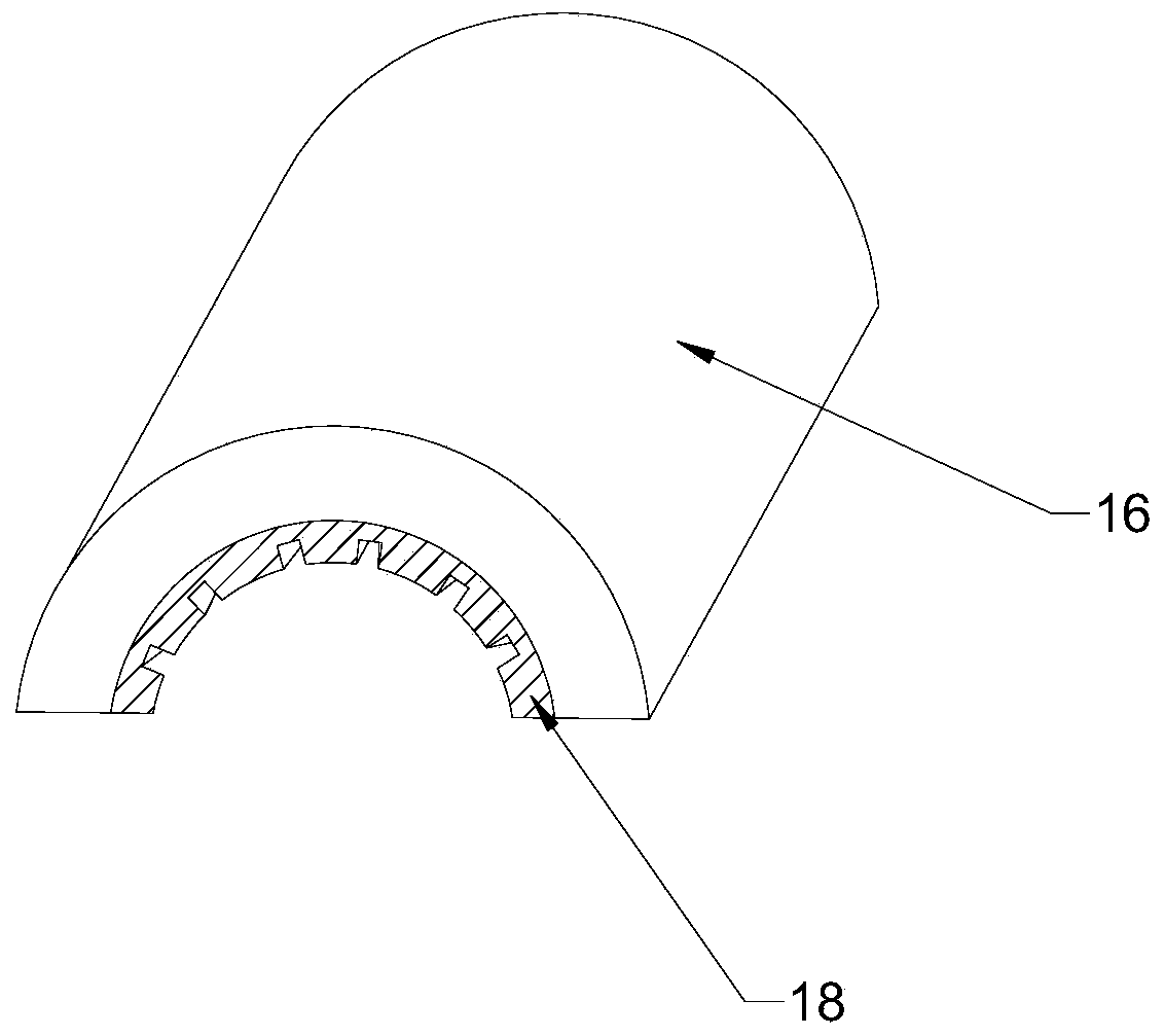
[0024] The difference between this embodiment and Embodiment 1 is that: the outer side of the cutting wheel 2 is provided with an extruding fixing mechanism, and the extruding fixing mechanism includes an extruding fixing plate 16, which is an arc-shaped plate, which can better stick To fit the tubular workpiece, the extruded fixed plate 16 is fixedly connected with the lifting plate 4 through the spring telescopic rod 17, so that the extruded fixed plate 16 moves up and down with the cutting wheel 2, and when the tubular workpiece is cut, the steel pipe is gradually extruded and fixed. Improve the stability of cutting, thereby ensuring the quality of the cut.

[0025] A rubber pad 18 is bonded to the inner side of the extruded fixing plate 16, and the rubber pad 18 is provided with strip-shaped anti-slip lines to improve friction, avoid steel pipes from slipping and rotating, and ensure cutting quality.


PUM


Abstract

The invention discloses a vertical cutting device for a tubular workpiece. The vertical cutting device comprises a cutting box, a cutting wheel and a conveying roller; the cutting wheel is rotatably connected with a protective cover through a rotating shaft, and the upper end of the protective cover is fixedly connected with a lifting plate; a group of connecting rods arranged symmetrically is hinged with the upper side of the lifting plate through hinge seats, and movable blocks are hinged with the upper ends of the connecting rods through hinge seats; each movable block is provided with a horizontal chute plate in a nesting mode, and each horizontal chute plate is internally provided with a two-way screw rod; and each two-way screw rod extends to the outer side of the cutting box, and isconnected with a screw rod motor through a coupling. According to the vertical cutting device, through arrangement of the lifting plate, the vertical chute plates, the connecting rods, the movable blocks moved face to face or oppositely, and the two-way screw rods, the cutting wheel can be used for automatic vertical cutting, and the cutting efficiency is improved; the incision quality is guaranteed; through arrangement of an extrusion fixing plate, a spring telescopic rod and a rubber pad, the extrusion fixing plate is moved with the lifting plate for extruding and fixing the cut tubular workpiece; and the cutting stability is improved, and the cutting quality is guaranteed.

Description

technical field [0001] The invention relates to the field of workpiece processing equipment, in particular to a vertical cutting device for tubular workpieces. Background technique [0002] The workpiece refers to the processing object in the machining process. It can be a single part or a combination of several parts fixed together. There are various types of workpiece processing methods, such as turning, milling, planing, grinding, casting, forging, etc. The machining process is a step in the manufacture and processing of workpieces or parts. The shape, size and surface of the blank are directly changed by the method of machining Quality, etc., the process of making it into parts is called machining process. For example, the processing process of an ordinary part is rough machining-finishing-assembly-inspection-packaging, which is a general process of processing. [0003] For the cutting of tubular workpieces, the traditional cutting machine adopts a semi-automatic meth...

Claims


Application Information

Patent Timeline
Patent Type & Authority Applications(China)
IPC IPC(8): B23D21/00B23D33/00B23D33/02
CPCB23D21/00B23D33/00B23D33/02
Inventor 赵言
Owner 赵言
Why Eureka
Try Eureka