Supercharge Your Innovation With Domain-Expert AI Agents!

Hydraulic transmission surface grinding machine

A surface grinder and hydraulic transmission technology, which is applied to the parts of grinding machine tools, grinding drive devices, grinding/polishing equipment, etc., can solve the problems of poor cylinder speed and stroke, time-consuming and labor-intensive operation, and low efficiency. Improve rigidity requirements, realize fine-tuning stroke, and increase the effect of tool setting function

Inactive Publication Date: 2012-07-25
盐城大丰远大机床有限公司
View PDF9 Cites 5 Cited by
  • Summary
  • Abstract
  • Description
  • Claims
  • Application Information

AI Technical Summary

Problems solved by technology

This transmission device has disadvantages in slow micro-adjustment, it is difficult to control the speed and stroke of the oil cylinder, and it is time-consuming and laborious to operate when fine-tuning the stroke
[0004] In addition, the traditional grinding tool setting mainly adopts manual methods such as listening to the grinding sound and watching the grinding sparks. These methods have the disadvantages of low efficiency and the accuracy of tool setting depends on the experience and proficiency of the operator.
In the transmission device of the surface grinder, because the speed and stroke of the oil cylinder are inconvenient to control, and the position of the workpiece to be processed on the worktable is arbitrary, it is difficult to achieve accurate tool setting
[0005] The patent authorization announcement number is CN202021511U, and the patent name is the invention of CNC vertical axis rectangular table surface grinder. It discloses a surface grinder including a CNC system. Its core technical feature is that the voltage signal is converted into torque and speed by a CNC servo motor to drive To control the grinding speed, the improvement of the technical solution is mainly used for the adjustment of the speed of the grinding machine table, and the problem of the control stroke of the transmission device in the slow micro-adjustment has not yet been solved

Method used


Image

  • Hydraulic transmission surface grinding machine
  • Hydraulic transmission surface grinding machine
  • Hydraulic transmission surface grinding machine

Examples


Embodiment Construction

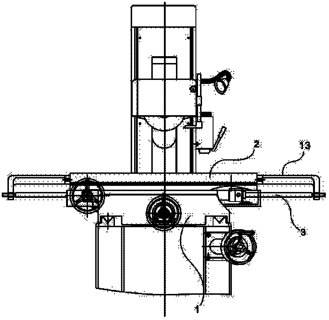
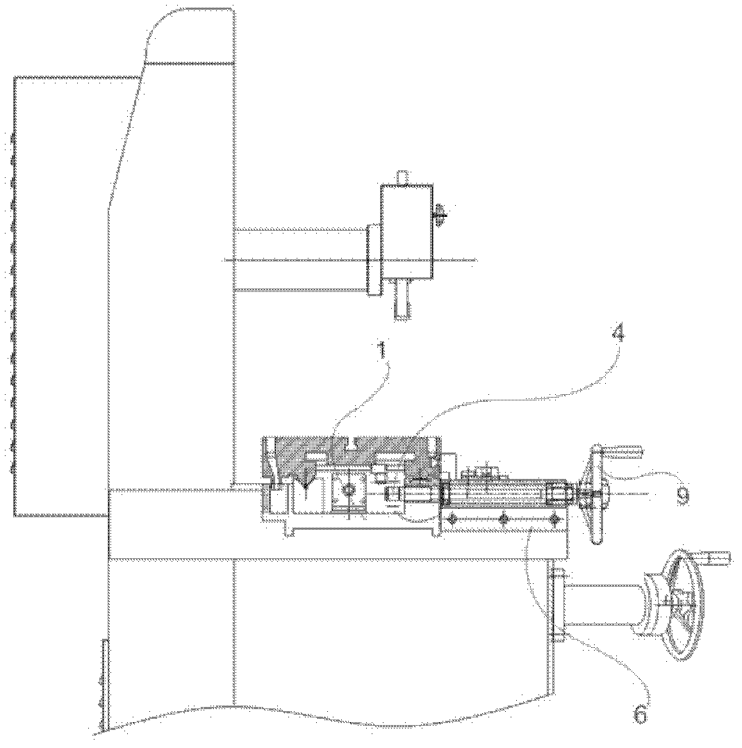
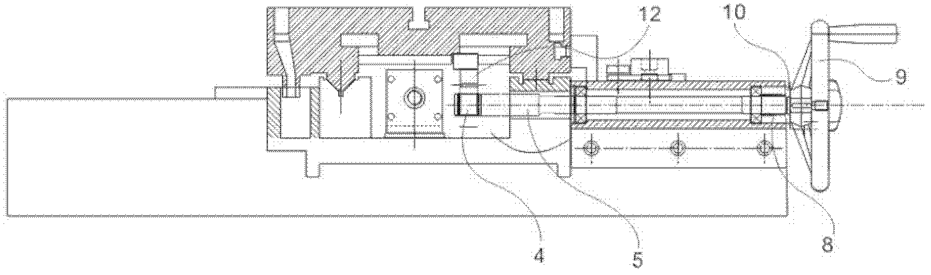
[0021] The present invention will be described in further detail below in conjunction with the accompanying drawings. Such as Figure 1-4 As shown in the figure, the grinder carriage 1, the hydraulic table 2, the oil cylinder 3, the fine-tuning gear 4, the transmission shaft 5, the bearing seat 6, the bearing 7, the elastic component 8, the hand-held rotation adjustment component 9, the elastic component Back-up ring 10, hydraulic valve speed regulation and start-stop handle 11, micro-movement rack 12, workbench oil cylinder connection pendant 13.

[0022] see Figure 1-4 As shown, the hydraulic transmission surface grinder proposed by the present invention includes a grinder carriage 1, a hydraulic workbench 2 and a manual adjustment device (not marked). The manual adjustment device includes a micro-movement rack 12 installed on the hydraulic workbench 2 and a mechanical drive device (not marked) installed on the grinding machine carriage 1 . The mechanical driving device ...


PUM


Abstract

The invention discloses a hydraulic transmission surface grinding machine, which comprises a grinding machine carriage, a hydraulic operating table and a manual adjusting device. The manual adjusting device comprises a micro-motion rack and a mechanical driving device, wherein the micro-motion rack is mounted on the hydraulic operating table, and the mechanical driving device comprises a fine adjusting gear and is mounted on the grinding machine carriage. The mechanical driving device can relatively move between an adjusting position and an idle position relative to the micro-motion rack, when the mechanical driving device is positioned at the adjusting position, the fine adjusting gear is meshed with the micro-motion rack, and the mechanical driving device can adjust the hydraulic operating table by means of meshing of the fine adjusting gear with the micro-motion rack, and when the driving device is positioned at the idle position, the fine adjusting gear is separated from the micro-motion rack. By mean of the ingenious structure design, the hydraulic transmission surface grinding machine is not only convenient in operation and capable of realizing automatic transmission of the operating table but also capable of realizing manual fine adjusting of stoke, and accordingly rigid demands of customers are greatly increased, a function of tool alignment is added, and intrinsic machining precision of work pieces is improved.

Description

technical field [0001] The invention relates to the field of machine tool manufacturing, in particular to a hydraulically driven surface grinder. Background technique [0002] The surface grinder uses a grinding wheel to grind the plane of the workpiece. Its grinding accuracy and roughness are relatively high, and it is a widely used machine tool. Among them, the small manual surface grinder is welcomed by the majority of users due to its light weight, small size, convenient operation and control, accurate precision, and high cost performance. Upgrading and transformation, innovation and improvement of the left and right movement of the grinding machine table, realized the conversion of the grinding machine table from manual to hydraulic transmission, and transformed the small manual surface grinder into a hydraulic transmission grinder. [0003] Hydraulic transmission is based on the liquid pressure energy in the sealed container for energy conversion, transmission and con...

Claims


Application Information

Patent Timeline
Patent Type & Authority Applications(China)
IPC IPC(8): B24B47/14
Inventor 陈慧峰任广宇宋丽琴
Owner 盐城大丰远大机床有限公司
Features
  • R&D
  • Intellectual Property
  • Life Sciences
  • Materials
  • Tech Scout
  • Unparalleled Data Quality
  • Higher Quality Content
  • 60% Fewer Hallucinations
Learn More