
Thin-walled centrifugal concrete pole manufacture method

A manufacturing method and technology of cement poles, applied in the fields of cement light poles, cement communication poles, cement poles, and cement pipe piles, can solve the problems of large shrinkage deformation, affecting the overall strength of thin-walled cement poles, and high cement content. , to achieve the effect of ensuring the overall strength

Active Publication Date: 2012-07-25
元工能源科技集团有限公司
View PDF4 Cites 2 Cited by
  • Summary
  • Abstract
  • Description
  • Claims
  • Application Information

AI Technical Summary

Problems solved by technology

When making thin-walled cement rods, because the aggregate particle size of concrete is generally small and the cement content is high, if the above-mentioned process is used, the shrinkage and deformation generated during the concrete solidification after centrifugation will be large, and micro-cracks will easily occur, which will affect the thin-walled cement. overall strength of the rod

Method used

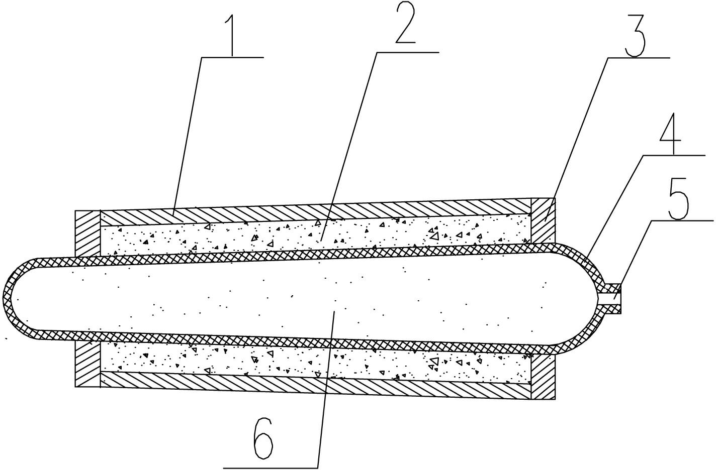

Image

  • Thin-walled centrifugal concrete pole manufacture method
  • Thin-walled centrifugal concrete pole manufacture method
  • Thin-walled centrifugal concrete pole manufacture method

Examples


Embodiment 1

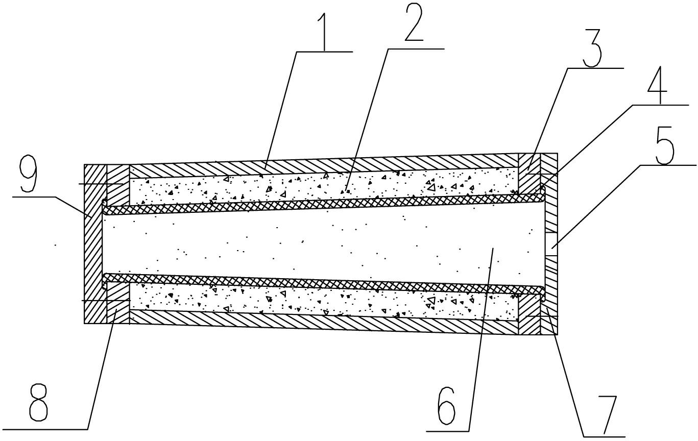
[0021] Such as figure 2 As shown, as an embodiment, the soft pressurized membrane 4 of the present invention is composed of a soft pressurized membrane sealing cover II7 with a medium injection port 5 at one end, and a conical tube or a circular tubular structure with an opening at the other end. One end of the body 1 is provided with a soft pressurized membrane sealing cover I9, and the opening end of the tapered tube or circular tubular soft pressurized membrane is sealed by the soft pressurized membrane sealing cover I9 with the end cover I8 on the centrifugal mold body 1 through bolts To connect, after the soft pressurized membrane of the tapered tube or circular tubular structure has the pressurized membrane seal cover II7 with the medium injection port 5 and the other end cover II3 on ​​the centrifugal mold body are fixedly connected by bolts, the When the pressurized medium 6 is injected into the soft pressurized film 4 of the conical or circular tubular structure, the...

Embodiment 2

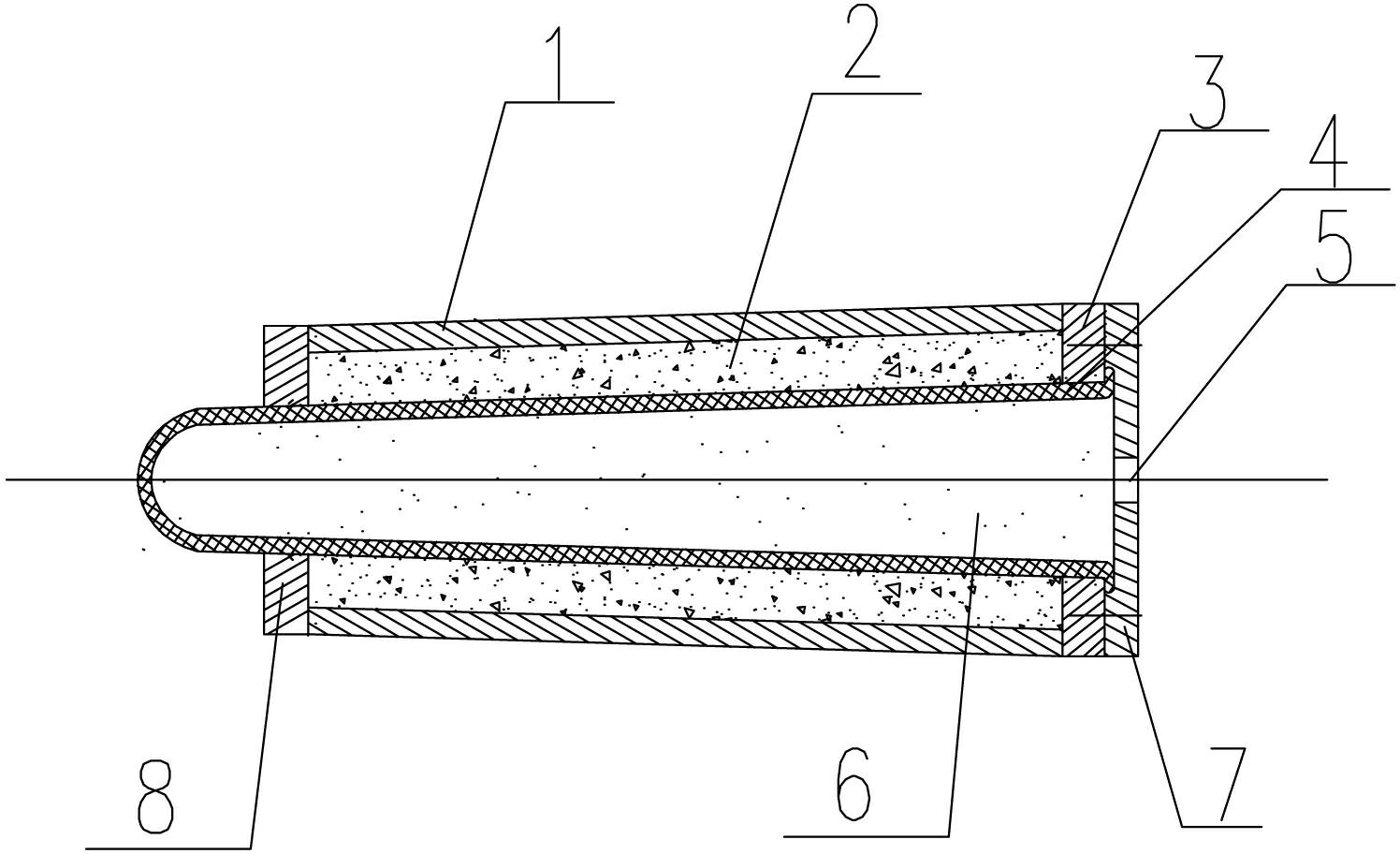
[0023] Such as image 3 As shown, as an embodiment, the soft pressurized membrane of the present invention is composed of a soft pressurized membrane sealing cover 7 with a medium injection port 5 at one end, and a barrel-shaped structure with an arc-shaped head at the other end. The pressurized film sealing cover 7 end with the medium injection port 5 is fixedly connected with the end cover II at one end of the centrifugal mold body 1 through bolts, and the arc-shaped end of the sealing head extends out of the other end cover I of the centrifugal mold body 1. When the pressurized medium 6 is injected into the soft pressurized film 4 of the barrel-shaped structure, the barrel-shaped soft pressurized film with an arc-shaped head and the pressurized film seal cover with a medium injection port together form an injection pressurized Closed cavity for media. The soft pressurized membrane 4 of this structure is relatively convenient to operate, and its pressurized pressure is 0.2-...


PUM


Abstract

The invention relates to a thin-walled centrifugal concrete pole manufacture method, which includes the steps: manufacturing a reinforcing rib framework, placing the reinforcing rib framework and stirred concrete into a centrifugal mould, rotating a centrifuge so that the concrete is uniformly distributed on the inner wall of the centrifugal mould to form a thin-walled centrifugal concrete pole wet green, taking the centrifugal mould down from the centrifuge, and solidifying the thin-walled centrifugal concrete pole wet green prior to steam curing and cooling demoulding. The method is characterized in that solidification of the thin-walled centrifugal concrete pole wet green is realized by leading a soft pressurizing membrane longer than the thin-walled centrifugal concrete pole wet green, made of plastics or rubber and provided with a media injection port into a central hollow cavity of the concrete pole wet green, adding pressurizing media so that the soft pressurizing membrane forms a closed cavity, keeping pressure of the pressurizing media until the concrete is solidified, emptying the pressurizing media, and taking the soft pressurizing membrane out prior to steam curing and cooling demoulding. The thin-walled centrifugal concrete pole manufacture method effectively avoids possibility of micro-cracks generated due to contraction distortion of the concrete for manufacturing a thin-walled concrete pole during solidification, so that the integral strength of the thin-walled concrete pole is improved.

Description

technical field [0001] The invention relates to the technical field of manufacturing cement electric poles, cement communication poles, cement lamp poles and cement pipe piles, in particular to a method for manufacturing thin-walled centrifugal cement poles. Background technique [0002] At present, the general method of manufacturing cement rods is mainly made by centrifugal molding process. Specifically, the prepared reinforcing rib skeleton is first put into the centrifugal mold, and then the mixed concrete is put into the mold, and the mold is adjusted and placed in the centrifugal mold. On the centrifuge, the rotating centrifuge makes the concrete evenly distributed on the inner wall of the mold, and the reinforcement skeleton is embedded in it at the same time. Remove the mold from the centrifuge, steam curing after the concrete is solidified, and then cool and demould to complete the main production process. When manufacturing thin-walled cement rods, the aggregate p...

Claims


Application Information

Patent Timeline
Patent Type & Authority Applications(China)
IPC IPC(8): B28B21/92
Inventor 祁锦明
Owner 元工能源科技集团有限公司
Learn More