Vehicle fuel tank and power system configuration

A power system and vehicle technology, which is applied to the arrangement of multiple different prime movers of power units, pneumatic power units, and general power units, etc., can solve the problems of single heat dissipation equipment, crowding, and difficult design of fuel tank positions, and achieve both Effect of improving space availability, safety, and availability

Inactive Publication Date: 2016-03-16
KYMCO
View PDF7 Cites 0 Cited by
  • Summary
  • Abstract
  • Description
  • Claims
  • Application Information

AI Technical Summary

Problems solved by technology

This will cause difficulties in designing the position of the fuel tank. If it is considered to install cooling equipment separately, it will also cause a single cooling equipment to be installed on both sides of the frame. In terms of space usage, it will be too crowded. If it is used in today’s all-terrain Four-wheel off-road vehicles (AllTerrainVehicle, ATV) or utility vehicles (UtilityVehicle, UV) will also be limited by the above-mentioned lack

Method used


Image

  • Vehicle fuel tank and power system configuration
  • Vehicle fuel tank and power system configuration
  • Vehicle fuel tank and power system configuration

Examples


Embodiment Construction

[0041] The embodiments of the present invention are described in detail below with reference to the drawings, and the attached drawings are all simplified schematic diagrams, and only schematically illustrate the basic method or structure of the present invention. Therefore, only components or steps related to the present invention are marked in these diagrams, and the displayed components or steps are not drawn with the number, shape, size ratio, etc. during implementation, and the specifications and sizes during actual implementation are actually one An optional design, and its component layout form or the number of steps may be more complex.

[0042] The orientations mentioned in the embodiments of the present invention are relative orientations based on the driver on the driver's seat, which will be described first.

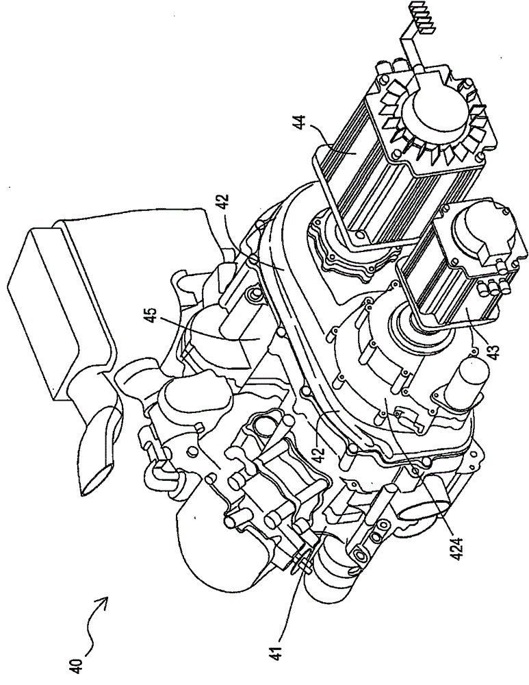
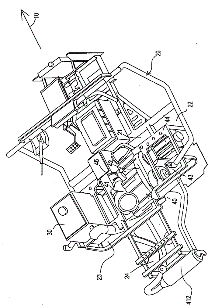
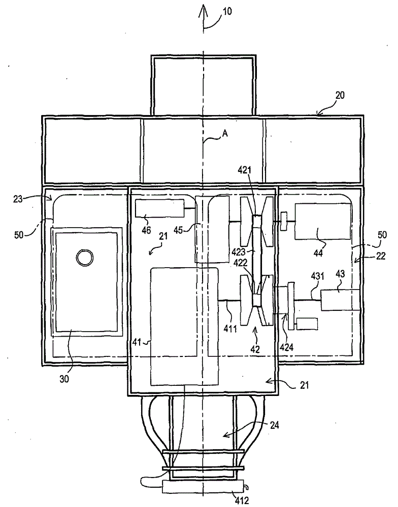
[0043] Please refer to figure 1 The three-dimensional schematic diagram of the embodiment of the power system of the present invention, figure 2 The three...


PUM


Abstract

The invention relates to configuration of an oil tank and a power system, which is suitable to use on a frame of a vehicle. The power system comprises an engine, a continuous variable speed transmission, a starting and generating device, a power motor, a retarding mechanism and a wheel shaft. The engine is provided with a crankshaft, the continuous variable speed transmission is provided with a driving shaft, a driven shaft and a belt, the starting and generating device is used for starting the engine or generating the electricity, the power motor is connected with the continuous variable speed transmission, the retarding mechanism is connected with the driven shaft and the wheel shaft is connected with the retarding mechanism, wherein the frame is provided with a main body part, a frist side part and an opposite second side part; the engine and the continuous variable speed transmission are arranged on the main body part; the starting and generating device and the power motor are positioned at the first side part; and the oil tank is positioned at the second side part.

Description

【Technical field】 [0001] The present invention relates to a hybrid vehicle, in particular to the configuration of a fuel tank and a power system on the vehicle frame of a hybrid utility vehicle or a hybrid all-terrain vehicle. 【Background technique】 [0002] In recent years, with the rise of the world's environmental protection awareness and the impact of the energy crisis, advanced countries in the world have invested a lot of money and manpower in research and development of low-pollution, low fuel consumption, and high-efficiency vehicles. [0003] Take the current emerging electric vehicle as an example, which uses electric energy as its driving energy and has no exhaust gas emissions and pollution, so it is considered the best means of transportation. However, electric vehicles have the disadvantages of low battery life, inconvenient charging, and high cost. In order to capture the advantages of electric vehicles and gasoline vehicles, vehicles with hybrid power system...

Claims


Application Information

Patent Timeline
Patent Type & Authority Patents(China)
IPC IPC(8): B60K6/24B60K6/40
CPCB60K15/063B60L2220/50Y02T10/64
Inventor 赖建宏张森宪苏川铭
Owner KYMCO
Why Eureka
Try Eureka