Magnetic levitation self-driven double-spiral-wing flying saucer

A magnetic levitation and dual-rotor technology, applied in the field of aviation aircraft, can solve problems such as faults, contact between rotors and disc shells, and achieve the effects of overcoming energy consumption, reasonable layout, and avoiding contact and friction

Inactive Publication Date: 2012-07-25
BEIJING UNIV OF TECH
View PDF9 Cites 16 Cited by
  • Summary
  • Abstract
  • Description
  • Claims
  • Application Information

AI Technical Summary

Problems solved by technology

[0005] When the rotor rotates at high speed in the disc shell, due to factors such as the aerodynamic vortex, the flexibility of the rotor, and the maneuvering flight of the flying saucer, the contact between the rotor and the disc shell may occur, causing malfunctions and even serious accidents. For details, see CN 1120008A, There are disadvantages as mentioned above

Method used


Image

  • Magnetic levitation self-driven double-spiral-wing flying saucer
  • Magnetic levitation self-driven double-spiral-wing flying saucer
  • Magnetic levitation self-driven double-spiral-wing flying saucer

Examples


Embodiment Construction

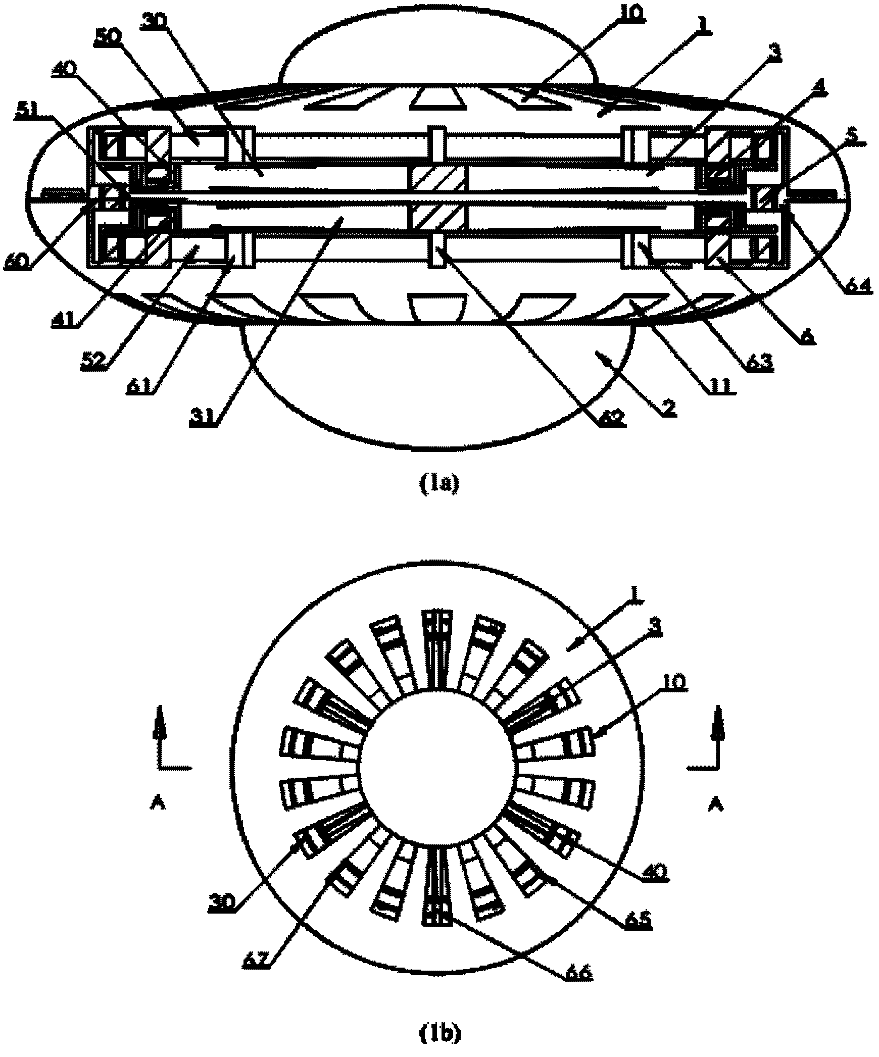
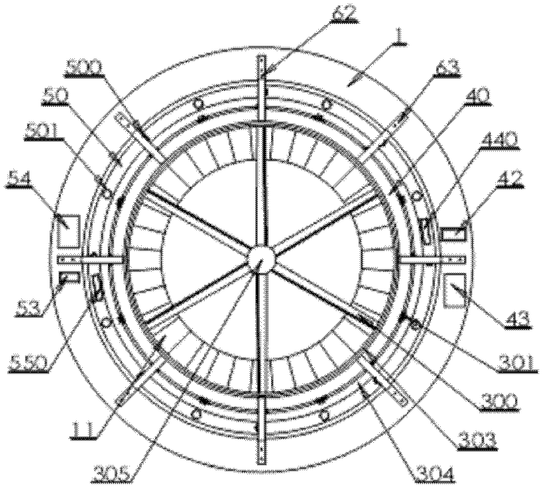
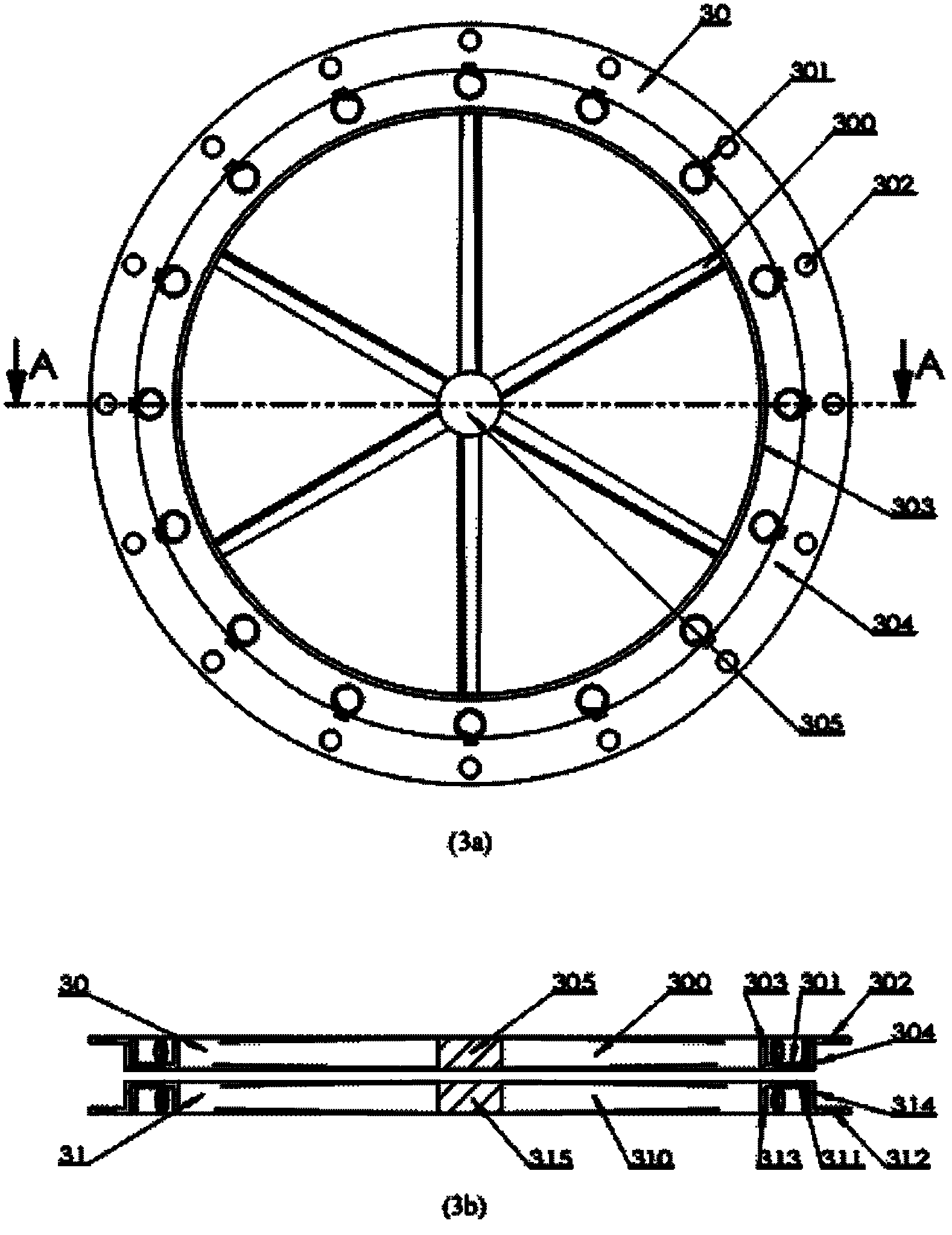
[0056] A magnetically suspended self-propelled dual-rotor flying saucer of the present invention includes: a disc shell 1, a disc cabin 2, a dual-rotor system 3, an excitation system 4 and a rotor positioning system 5, and it is characterized in that the dual-rotor system 3 is a magnetically suspended self-driving The drive system consists of two upper and lower maglev rotor wheels 30, 31 with similar structures arranged coaxially along the vertical direction of the dish coordinate system, wherein the upper maglev rotor wheel 30 consists of an upper maglev rotor wheel blade 300, an upper maglev rotor Wheel induction coil 301 / 311, upper maglev rotor wheel positioning permanent magnet piece 302 / 312, upper maglev rotor wheel blade end ring 303, upper maglev rotor wheel Z-shaped positioning disc 304 and upper maglev rotor wheel hub 305; The magnetic levitation rotor wheel 31 is composed of a lower magnetic levitation rotor wheel blade 310, a lower magnetic levitation rotor wheel in...


PUM


Abstract

The invention relates to a magnetic levitation self-driven double-spiral-wing flying saucer, which consists of a saucer housing, a saucer cabin, a double-spiral-wing system, an excitation system and a spiral wing positioning system. Upper and lower magnetic levitation spiral wing wheels in the double-spiral-wing system rotate relatively through interactive magnetic forces generated by a magnetic field generated by -inductive current in inductive coils to realize self-driven rotation. An excitation controller in the excitation system controls the speed of the self-driven rotation by measuring relative position change of a positioned magnetic field on the upper and lower magnetic levitation spiral wing wheels and changes the direction of -control current in a control circuit -to change the direction of the inductive magnetic field in the spiral wing wheels so as to control steering of the self-driven rotation. The magnetic levitation self-driven double-spiral-wing flying saucer has the advantages of compact design structure, reasonable layout, light weight, and high power conversion efficiency, overcomes the reverse torque deficiency of the spiral wing flying saucer at the same time, and realizes positioning control of the spiral wing and guarantees safe operation of the flying saucer.

Description

technical field [0001] The invention belongs to the field of aviation aircraft, and in particular relates to a magnetically suspended self-driven double-rotor flying saucer. technical background [0002] The lift and thrust of the rotorcraft are formed by the high-speed rotating rotor, and the power of the rotor rotation comes from the engine and other electromagnetic power devices. Existing rotorcrafts, including various rotor helicopters, have rotors driven by engines or other electromagnetic power devices to rotate, and the anti-torque force of the rotors reacts against the engines or electromagnetic power drives, and finally acts on the body. Affected by the reaction torque, an auxiliary mechanism is often needed to counteract the torsion to ensure the body posture. [0003] Compared with the general rotorcraft, the particularity of the rotorcraft is that the rotor system and its power system of the rotorcraft need to be installed in the disc shell. The internal space ...

Claims


Application Information

Patent Timeline
Patent Type & Authority Applications(China)
IPC IPC(8): B64C39/06
Inventor 阮晓钢侯旭阳赵秉辉奥塔瓦・谢朱晓庆
Owner BEIJING UNIV OF TECH
Why Eureka
Try Eureka