Integrated construction equipment for binding and lifting continuous beam steel reinforcement framework and construction method

A steel frame and beam steel bar technology, which is applied to the integrated construction equipment and construction field of continuous beam steel frame binding and hoisting, can solve the problems of narrow operating space for hanging baskets, high construction costs, and inability to work in parallel, so as to save time for steel bar binding, The effect of shortening the construction time and eliminating potential safety hazards

Active Publication Date: 2012-07-25
THE FIRST ENG CO LTD OF CTCE GRP
View PDF7 Cites 7 Cited by
  • Summary
  • Abstract
  • Description
  • Claims
  • Application Information

AI Technical Summary

Problems solved by technology

[0003] 1. Due to the narrow operating space inside the hanging basket, it is difficult to control the quality of steel bar binding;
[0004] 2. In the construction of continuous beams, the steel bar binding operation process can only be carried out in the entire continuous beam construction, and cannot be operated in parallel, which takes up a lot of time and prevents the construction period from being effectively shortened.
[0006] 1. In order to complete the lashing and overall hoisting outside the site, it is necessary

Method used


Image

  • Integrated construction equipment for binding and lifting continuous beam steel reinforcement framework and construction method
  • Integrated construction equipment for binding and lifting continuous beam steel reinforcement framework and construction method
  • Integrated construction equipment for binding and lifting continuous beam steel reinforcement framework and construction method

Examples


Embodiment Construction

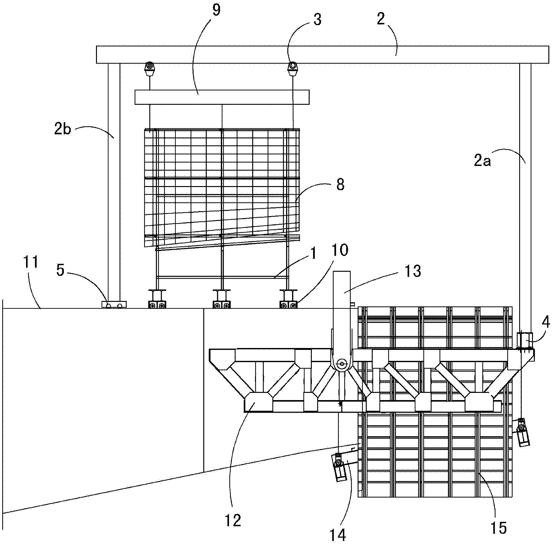
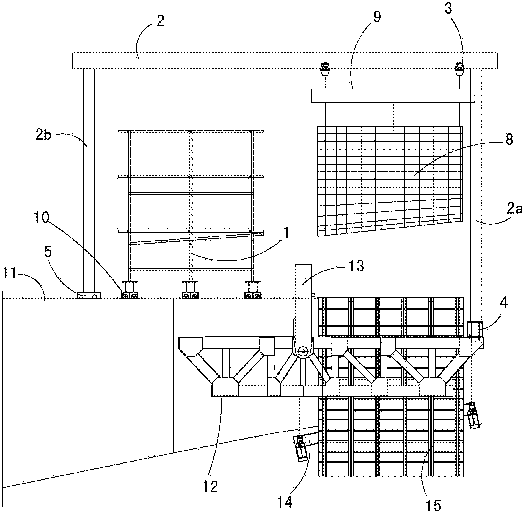
[0032] see figure 1 and figure 2 , this embodiment is aimed at the under-supported hanging basket in the bridge construction disclosed in the utility model with the publication number of 201972099U. Composed together with the side form 15, the main truss 12, the front upper beam 4 and the rear upper beam 13 play a supporting role in the concrete pouring process, and the bottom form 14 and the side form 15 are concrete pouring formwork.

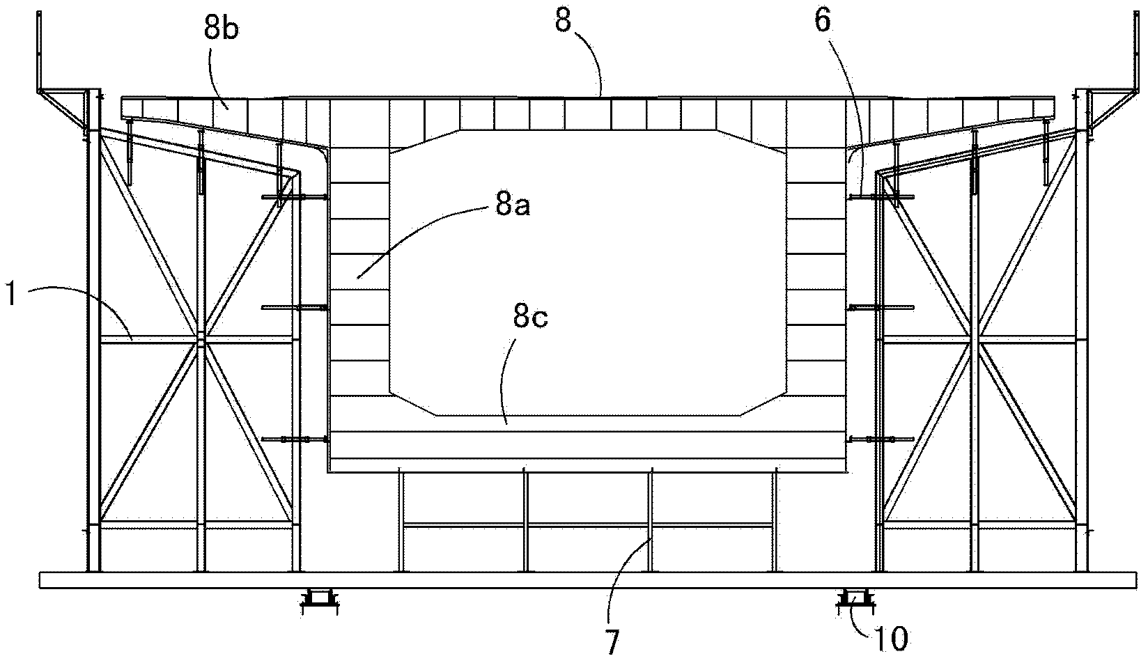
[0033] In specific implementation, such as figure 1 and figure 2 , on the poured beam surface 11, a steel bar binding mold 1 for binding the steel bar skeleton 8 is arranged; a truss-type sliding spreader 2 is arranged longitudinally above the steel-bar binding mold 1, and the front end of the truss-type sliding spreader 2 passes through the front end The bracket 2a is supported on the upper beam 4 in front of the hanging basket, and the tail end is supported on the poured beam surface 11 through the tail bracket 2b; the crane 3 is instal...


PUM


Abstract

The invention discloses integrated construction equipment for binding and lifting a continuous beam steel reinforcement framework. The integrated construction equipment is characterized in that a steel reinforcement binding fixture for binding the steel reinforcement framework is arranged on a cast bridge floor, a truss-type slide lifting appliance is longitudinally arranged above the steel reinforcement binding fixture, the front end of the truss-type slide lifting appliance is supported on a front upper beam of a cradle through a front end support, the tail end of the truss-type slide lifting appliance is supported on the cast bridge floor through a tail support, a crown block is mounted on the truss-type slide lifting appliance, and the steel reinforcement framework can be integrally lifted via a steel reinforcement hanger lifted by the crown block. The steel reinforcement binding fixture is mounted on the constructed bridge floor and used for binding the steel reinforcement framework, steel reinforcements are lifted into the cradle by the truss-type slide lifting appliance, steel reinforcement binding and beam section construction are realized simultaneously, and construction time is greatly shortened.

Description

technical field [0001] The invention relates to construction equipment and a construction method for binding, hoisting and installing steel bar skeletons in the construction of continuous beam hanging baskets, and is especially applied in the construction of continuous beams of down-supported hanging baskets. Background technique [0002] In the construction of continuous beams, the traditional construction method is to use the upper hanging basket, and the steel bars are bound inside the hanging basket on site. This method has the following problems: [0003] 1. Due to the narrow operating space inside the hanging basket, it is difficult to control the quality of steel bar binding; [0004] 2. In the construction of continuous beams, the steel bar binding operation process can only be carried out in the flow of the entire continuous beam construction, and cannot be operated in parallel, which takes up a lot of time and makes the construction period unable to be effectively ...

Claims


Application Information

Patent Timeline
IPC IPC(8): E01D21/10
Inventor 梁超刘武生李彬程静敏张宏斌万继庚
Owner THE FIRST ENG CO LTD OF CTCE GRP
Why Eureka
Try Eureka