Modular building construction

a building construction and module technology, applied in the field of construction, can solve the problems of increasing construction time, manual labor, and large use of materials, and achieve the effect of high rigidity and easy and quick erection of building structures

Inactive Publication Date: 2013-06-11
IVANOV NIKOLAY VASKOV
View PDF45 Cites 29 Cited by
  • Summary
  • Abstract
  • Description
  • Claims
  • Application Information

AI Technical Summary

Benefits of technology

[0009]An object of the present invention is to provide a construction system as well as a building construction module which can guarantee easy and quick erection of building structures with high rigidity and great variety of spatial solutions.
[0010]The proposed construction system comprises plurality of elongated flat elements of equal thickness c, each of the flat elements having slots at least on one of the long sides through the whole thickness c of the elements and the slots are located in such a way so that the flat elements can intersect each other through the slots in order to form a grid with total height equal to the width d of the flat element with the biggest width. At least two flat elements of the system have slots located at equal distances n from each other. At least two flat elements have slots located at equal distance b from each other where the ratio n:b is within the range from 1:1 to 1:10. In one of the preferred embodiments the ratio n:b is within the range from 1:1.5 to 1:10. At least two flat elements have at least two slots located at distance e from each other and at least two other flat elements have at least two slots located at distance A, where the distances e and A are independent of each other and they are independent of the distance n, where each of the distances e and A is within the range from 0.2b to 10b. The slots at the ends of at least two flat elements are at distance h equal to at least 0.5 n from the edge of the short side of the element. The advantage of this system is that its elements are structurally independent of the thickness “c” and, therefore, from the type of the material used. It may be constructed uniform grids having openings equal in dimensions and area which leads to even distribution of loads allowing for the use of thinner distribution layer transferring the direct loads to the grid. It may be constructed irregular grids having unequal openings, depending of the requirements. Moreover, steady three-dimensional (3D) frameworks of the building structures of grid type can be easily and quickly erected using the elements of the so described construction system, where the density of the grid can be chosen depending on the requirements for load bearing capacity. Construction modules with compatible grids of different density multiple to n and b for the floor and the ceiling can be constructed which can penetrate into each other when two construction modules are connected in height. The wall grids can have different density thus providing the possibility for forming window areas to meet specific requests. This allows the reducing of the wet processes in construction which decreases the time of construction. Besides, this allows for the production of prefabricated 3D modular construction cells. This also ensures great variety of architectural spatial solutions. The system can be used for covering big spans without using other type of support and the structure is extremely rigid. The elements can be unified which allows reducing their number.
[0011]In one embodiment of the present invention, the construction system comprises at least two flat elements with slots on the two long sides located in a chess-board order and the distances between the slots on each of both sides are equal to b. The system may comprise also at least two flat elements with slots on the two long sides located in a chess-board order and the distances between the slots on each of both sides are equal to e as well as at least two flat elements with at least one transversal slot with width equal to at least 2c. Such implementation of the flat elements increases the system possibilities for construction of a next story or semi-story in height, for construction of stabilizing girdles as well as the possibilities for large cantilever projections.

Problems solved by technology

Some problems have been outlined in the use of prefabricated modular elements and three-dimensional (3D) section modules in the construction.
These construction systems have the following disadvantages: a lot of material is used for them; the structures are very heavy and are not appropriate for prefabrication of 3D modular construction sections which increases the time of construction.
The main disadvantage of such construction modules with frame structures is that a lot of material is used for their production and that they can be connected to each other by laying concrete on the joints in-situ.
A lot of manual labour is used which increases the construction time.
Moreover, they do not provide sufficient rigidity of the construction module.
These types of grids can be used in the in-situ construction of buildings but they cannot be used for 3D building structures as they do not allow joining elements in height.
They can be used in construction but they cannot be used for construction of 3D building construction modules as they do not allow joining elements in height.
Besides, in this system the constructed grid have sections with different dimensions and area which leads to uneven loadings and requires thicker distribution layer transferring the direct loads on the grid.
A disadvantage of the prior art system is that it cannot be used for construction of 3D space construction modules as it does not allow joining additional elements in height.
Another disadvantage is that the constructed grid structure cannot be effectively used in designing the interior spaces.
This method cannot be used for construction of 3D space building structures and for production of prefabricated construction modules.
The method is labour-intensive and slow.

Method used


Image

  • Modular building construction
  • Modular building construction
  • Modular building construction

Examples


Embodiment Construction

[0046]The present invention is demonstrates in the attached figures and is visualized by the examples below which serve only as illustration.

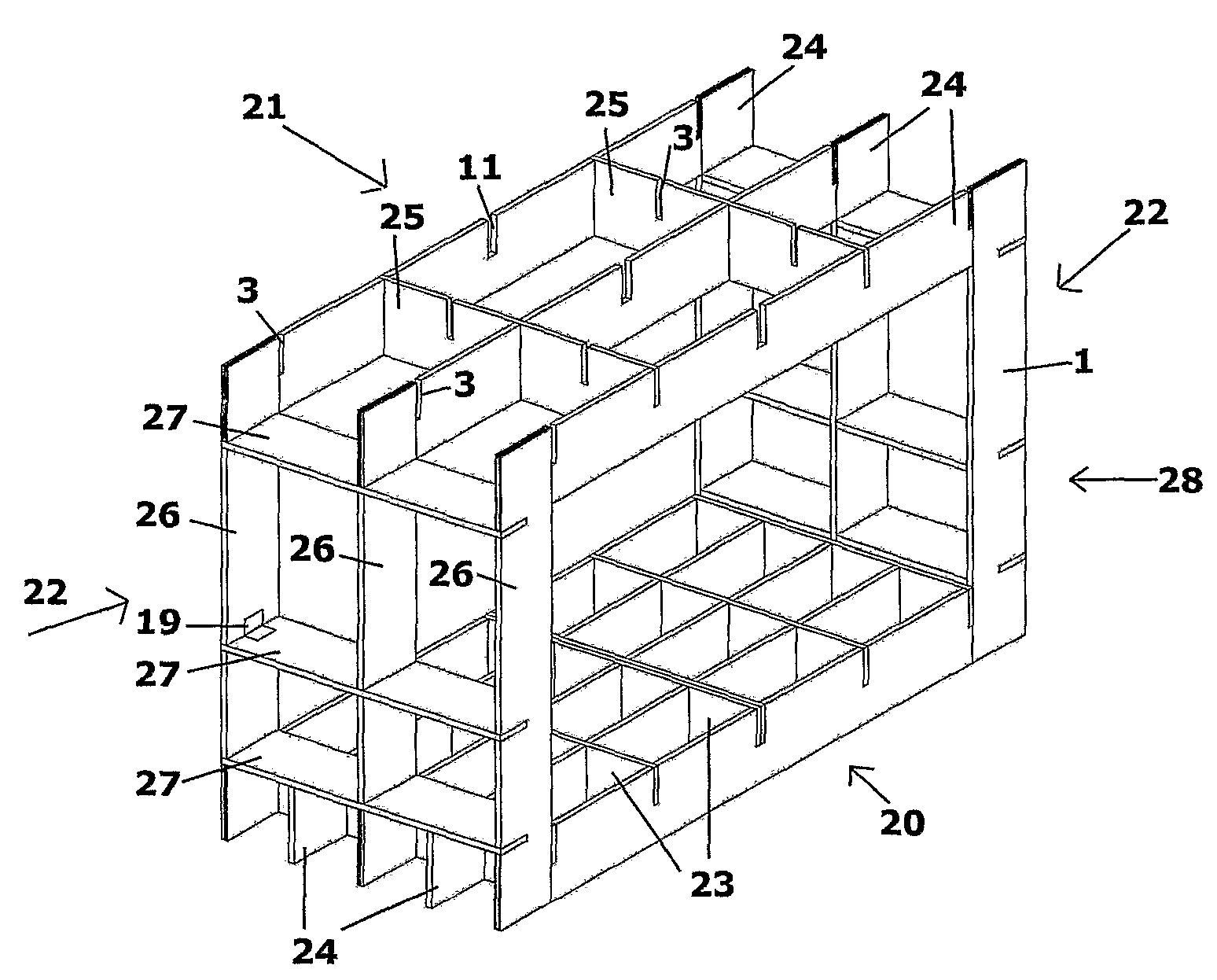
[0047]The construction system includes elongated flat elements. It can also include flat frames.

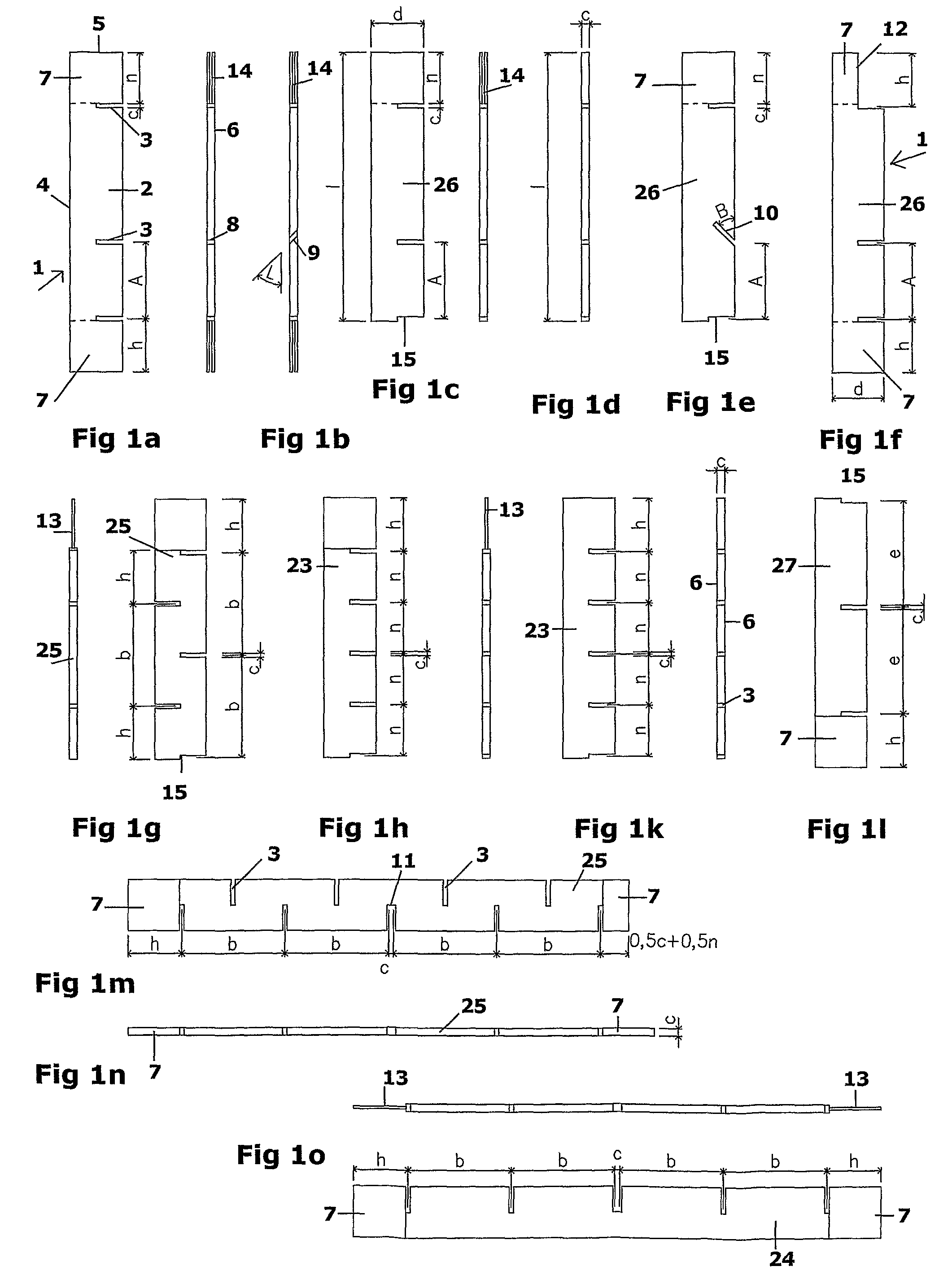
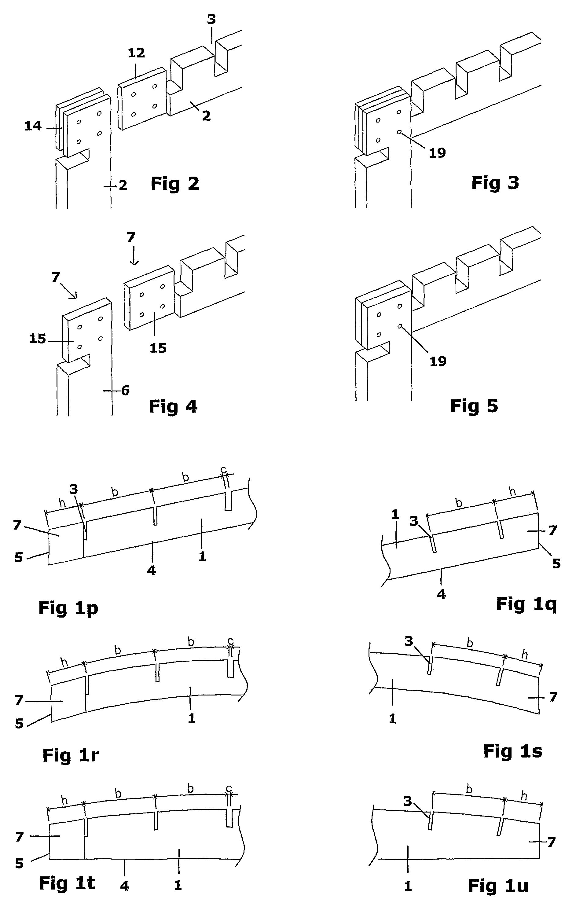
[0048]Different embodiments of elongated flat elements 1 which together or separately, in different combinations, can form system elements are presented in FIGS. from 1a to 1u. The flat elements 1 can be rectangular (FIGS. 1a-1o), rhomboidal (FIGS. 1p-1q), curved (FIG. 1r, 1s) or arch-shaped (FIGS. 1t, 1u). Other shapes, not shown in the figures, like corrugated, triangular and other flat shapes depending on the specific architectural project are also possible. The flat elements can have different length l and different width d. Each flat element 1 includes a body 2 and slots 3. The bodies 2 have long sides 4 which constitute the element length l as well as short sides 5 constituting the element width d. The long sides 4 and the short sides 5 form tw...


PUM


Abstract

The invention relates to the field of construction and in particular to a modular construction system used for building of construction modules. The construction system comprises plurality of flat elements (1) with identical thickness C and having slots (3) on at least one of its long sides (4), as the slots (3) are located at a distance from each other so that the flat elements (1) can intersect each other through their slots (3) in order to form a grid. The elements (1) of the system have slots (3) located at equal distances n or b from each other where the ratio n:b is within the range from 1:1 to 1:10. The building construction module is made as three-dimensional frame structure shaped like polyhedron including a floor (20), a ceiling (21) and at least two walls (22) grids connected together. The grids are made by intersecting through slots (3) flat elements (1).

Description

FIELD OF THE INVENTION[0001]The present invention relates to the field of construction and in particular to a construction system, a building construction module and a method for building construction. The system can be applied in construction of buildings both by assembling of prefabricated horizontal and standing grids or prefabricated building construction three-dimensional modules, and by connection of the elements on the construction site. It is appropriate for use in the low-rise, middle-rise and high-rise buildings. The system can also be applied for production of construction toys as well as for making architectural models.BACKGROUND OF THE INVENTION[0002]There are a great number of construction systems using prefabricated elements. Their main advantage is that they ensure easy and quick construction and allow avoiding wet processes on the construction site. Ways and means for decrease of the construction costs as well as for provision of higher rigidity of the buildings hav...

Claims


Application Information

Patent Timeline
Patent Type & Authority Patents(United States)
IPC IPC(8): E04C2/42E04C5/04E04F15/06E04F19/10
CPCA63H33/084E04B1/18E04B1/348E04B2001/2409E04B2001/262
Inventor IVANOV, NIKOLAY VASKOV
Owner IVANOV NIKOLAY VASKOV
Why Eureka
Try Eureka