Building structure and construction method

A kind of building structure and combined technology, applied in the direction of building structure, construction, etc., can solve the problems of discounted bearing capacity, poor supporting bearing capacity, poor overall rigidity, etc., and achieve the effect of low cost, easy installation and fixing, and simple structure

Inactive Publication Date: 2012-07-25
杨东佐
View PDF8 Cites 32 Cited by
  • Summary
  • Abstract
  • Description
  • Claims
  • Application Information

AI Technical Summary

Problems solved by technology

This construction method has the following disadvantages: the construction period of the building is long; the on-site operations are greatly affected by weather and other natural conditions; It will inevitably affect the quality of the project, and it is difficult to ensure the quality of the project; the risk of manual production on site is high, which directly threatens the life safety of the workers; the structural construction of each floor is irreversible, and the quality of the next floor affects the quality of the project. The structural safety and stability of the upper floor; the singleness of the structural force often makes it difficult to ensure the overall safety of the building; from the perspective of utilization, it is a one

Method used


Image

  • Building structure and construction method
  • Building structure and construction method
  • Building structure and construction method

Examples


Embodiment 1

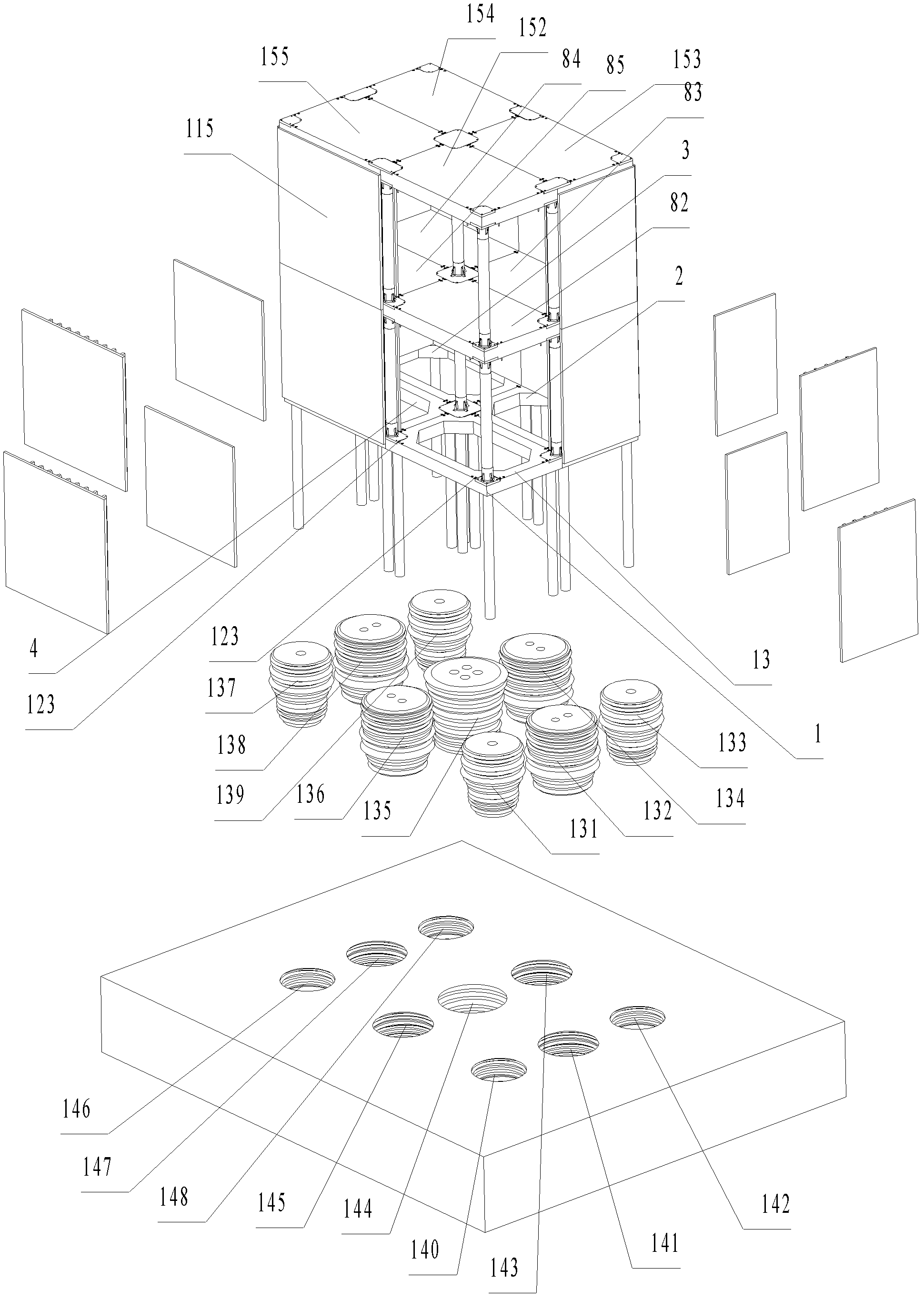
[0198] Such as figure 1 As shown, a house includes a square prefabricated frame 1 , a prefabricated frame 2 , a prefabricated frame 3 , and a prefabricated frame 4 that are spliced ​​in pairs on the ground floor and have the same structure.

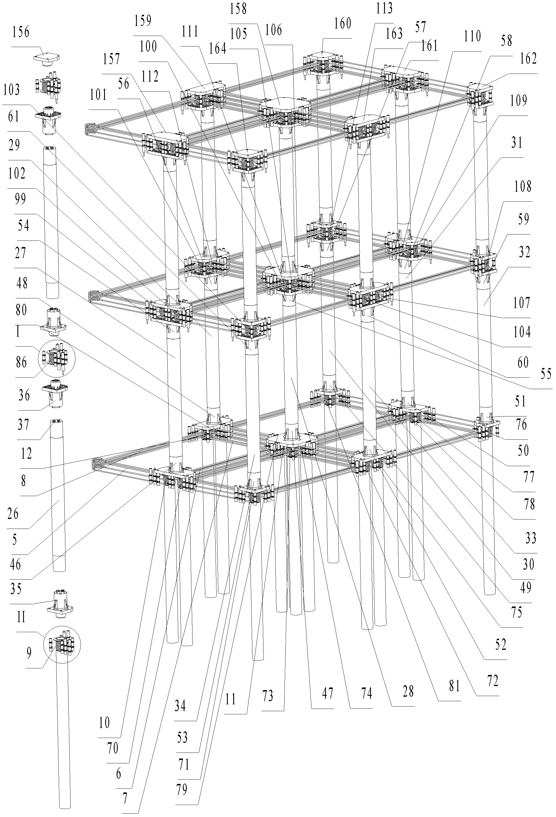
[0199] Such as figure 2 As shown, the prefabricated frame 1 includes a reinforced beam 5, a reinforced beam 6, a reinforced beam 7, and a reinforced beam 8 embedded in the prefabricated frame 1, corresponding to the four sides of the prefabricated frame 1, and each side is composed of four steel bars. , the pre-embedded connector 10 connecting the connection nodes at the ends of the reinforced beam 5 and the reinforced beam 6, the embedded connector 11 connecting the connected nodes at the ends of the reinforced beam 6 and the reinforced beam 7, connecting the reinforced beam 7 and the 8 ends of the reinforced beam The pre-embedded connector 12 of the connection node of the part, the pre-embedded connector 9 of the connection node conne...

Embodiment 2

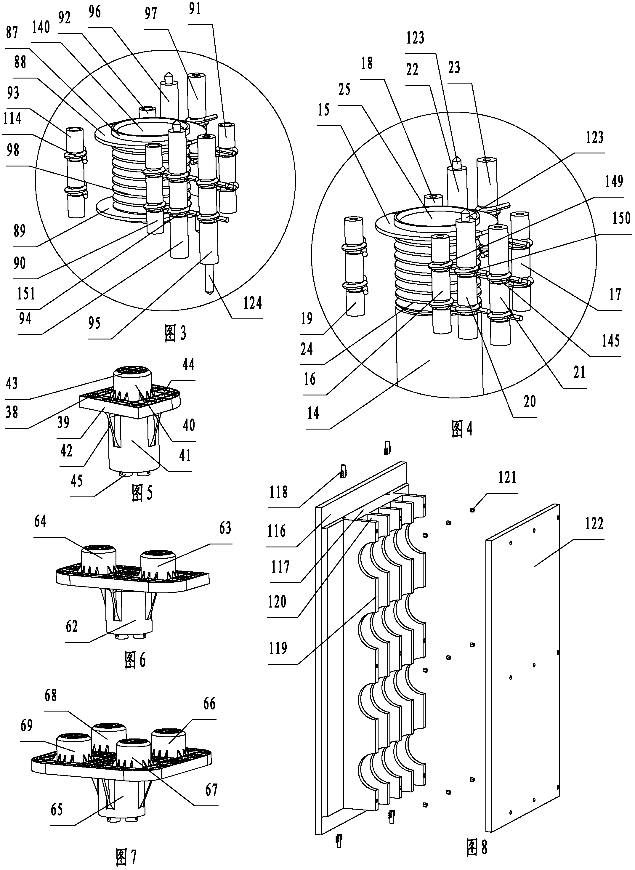
[0225] Such as Figure 9 to Figure 10 As shown, the difference from Example 1 is that each prefabricated frame on the bottom layer, each prefabricated board on the middle layer, and each prefabricated board on the top layer are bent and wound in the slots 171 of the round tubes of the embedded connectors. Resist steel bar 172. The lower end of the round tube of the embedded connector of each prefabricated panel on the top floor is the first positioning column 173 . The lower end of the round tube of the embedded connector of each prefabricated panel in the middle layer is the first positioning column 174 and the upper end is the first positioning column 175 . The upper end of the circular tube of the pre-embedded connector of each prefabricated frame on the bottom floor is the first positioning column 176, and the lower end of the circular tube of the pre-embedded connector is the short pipe pile 177 embedded in the ground. All the column connectors cooperate with the first ...

Embodiment 3

[0227] Such as Figure 11 As shown, the difference from Example 1 is that the upper end of the round tube of the embedded connector of each prefabricated frame on the ground floor, the upper end and lower end of the round tube of the embedded connector of each prefabricated panel in the middle layer 1. The upper end of the round tube of the embedded connector of each prefabricated panel on the top floor is a stepped part with a small end and a large middle part. An annular baffle 191 is set on the small end 190 of the stepped part. The baffle 191 One end surface is attached to the end surface of the big end 192 of the stepped part, and the baffle plate 191 is welded on the round pipe. All the round pipes of the pre-embedded connectors are not provided with a draw-in groove and two semi-circular baffles welded and fixed in the draw-in groove.


PUM


Abstract

Disclosed are a building structure and a construction method. The building structure comprises upright columns, prefabricated plates or prefabricated frames and columnar connecting parts. Each prefabricated plate or prefabricated frame comprises reinforced beams or section crossbeams and embedded connecting parts, wherein the reinforced beams or section crossbeams are embedded in the prefabricated plates or prefabricated frames, and the embedded connecting parts are arranged at connecting joints for connecting the reinforced beams or section crossbeams; the columnar connecting parts are mounted at connecting joints of the prefabricated plates or prefabricated frames; the number of the columnar connecting parts is smaller than or equal to that of the embedded connecting parts; each embedded connecting part comprises a first positioning mechanism; each columnar connecting part comprises one to four second positioning mechanisms matching with the corresponding first positioning mechanisms in a one-to-one correspondence manner; and the first positioning mechanisms and the corresponding second positioning mechanisms are vertically connected in an inserted manner, and the columnar connecting parts are fixed with the one to four embedded connecting parts at the connecting joints. The building structure and the construction method have the advantages that various portions of the building structure can be mechanically assembled and disassembled, can be reused, and are convenient in assembly and disassembly, and the connecting joints are firm and reliable in connection and fine in load-carrying capability.

Description

technical field [0001] The present invention relates to a building structure and a construction method such as houses, bridges, pavilions, etc., and particularly relates to a building structure and a construction method in which floors, wall panels, columns, etc. can be prefabricated in a factory and only need to be installed on site. Background technique [0002] At present, cast-in-place reinforced concrete foundations, columns, walls, beams, and slabs are commonly used in the construction of buildings as the main load-bearing structure. The enclosure mostly adopts masonry construction. This construction method has the following disadvantages: the construction period of the building is long; the on-site operations are greatly affected by weather and other natural conditions; It will inevitably affect the quality of the project, and it is difficult to ensure the quality of the project; the risk of manual production on site is high, which directly threatens the life safety ...

Claims


Application Information

Patent Timeline
IPC IPC(8): E04B1/00E04B1/04E04B1/19E04B1/41E04B1/58
Inventor 杨东佐
Owner 杨东佐
Why Eureka
Try Eureka