Gob-side entry retaining method for pouring spacing concrete walls in tunnel of advanced highwall

A technology for concrete walls and working faces, which is applied to mining equipment, earthwork drilling, shaft lining, etc. It can solve problems such as large roof sinking, heavy workload impact, and gas overrun, and achieve safe and reliable support, reduce The effect of high workload and support strength

Inactive Publication Date: 2012-07-25
王晓利
View PDF6 Cites 3 Cited by
  • Summary
  • Abstract
  • Description
  • Claims
  • Application Information

AI Technical Summary

Problems solved by technology

[0002] The traditional gob-side retaining method is to use gangue bags, wooden point columns, wooden stacks, concrete walls, high-water material walls or blocks to support the roadside in the goaf behind the coal mining face. The method of construction behind the coal mining face needs to set up single or wooden point columns in the goaf behind the hydraulic support for temporary support. This method cannot adapt to the broken roof during mining, the roof collapses immediately after the frame is pulled, or the roof sinks. In the case of a large amount, the reason is that the safety of the goaf operation is poor, or the temporary support strength is low, the roof sinking is large, the height of the entry is too small to meet the use requirements, and the workload of the one-time pouring of the concrete continuous wall behind the hydraulic support is large. recovery speed
For some high-gas mines with complex surrounding rock conditions on the roof of the coal seam, in order to solve the problem of gas exceeding the limit, relieve the tension, and recover the coal pillars, the fundamental method is to keep the roadway along the goaf, but the construction roadway in the goaf behind the working face There are many problems with side supports

Method used


Image

  • Gob-side entry retaining method for pouring spacing concrete walls in tunnel of advanced highwall
  • Gob-side entry retaining method for pouring spacing concrete walls in tunnel of advanced highwall
  • Gob-side entry retaining method for pouring spacing concrete walls in tunnel of advanced highwall

Examples


Embodiment Construction

[0019] Below in conjunction with accompanying drawing, content of the invention is further described:

[0020] refer to Figure 1-Figure 3 Shown:

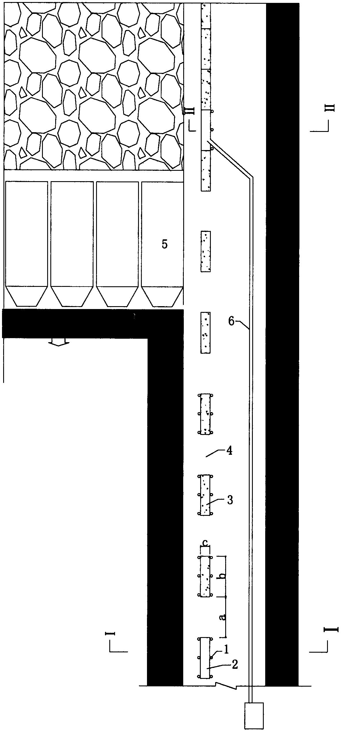
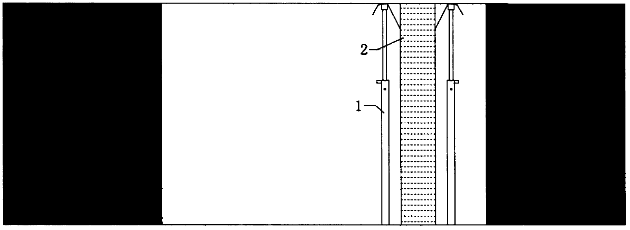
[0021] a. The advanced coal mining face is in the return air trough, and the flexible formwork 2 arranged at three to six intervals is suspended by the single pillar 1. The length b of the flexible formwork 2 is 1-3m, the width c is 0.2-2m, and the height The height of the roadway is the same, and the distance a between the flexible templates 2 is 1-6m.

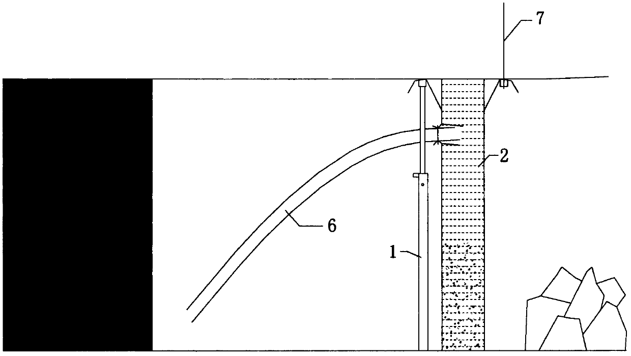
[0022] b. Fill concrete into three to six flexible formworks 2 sequentially through the concrete delivery pipe 6;

[0023] c. After the concrete is hardened, the single pillar 1 used to hang the flexible formwork 2 is removed, and a spaced concrete discontinuous wall 3 is formed in the return air channel of the advanced working face;

[0024] d. Advancing the coal mining face;

[0025] e. The lagging coal mining face is in the reserved roadway along the gob, and one to six fle...


PUM


Abstract

The invention discloses a gob-side entry retaining method for pouring spacing concrete walls in a tunnel of an advanced highwall. A plurality of flexible formworks which are arranged at intervals are hung in a return air laneway of the advanced highwall by single bodies or anchor rods, concrete is poured into the flexible formworks via a concrete pump, a spacing concrete wall is formed and clings to a roof, then the flexible formworks are hung in space intervals of the spacing concrete wall by a lagging work surface, the concrete is pumped into the flexible formworks, so that a closed concrete continuous wall is formed, and finally a gob-side entry is formed. The spacing concrete wall is poured in the advanced highwall to realize gob-side entry retaining, requirements of ventilation, recovery and construction are met, supporting is safe and reliable, and recovery is not affected. The method is suitable for crushing the roof to realize gob-side entry retaining during recovery, and is widely used for industries of coal mines, metallurgical mines and the like.

Description

technical field [0001] The invention relates to mining without coal pillars, in particular to a method for pouring spaced concrete walls along gob-side entry in an entryway of an advanced mining working face. Background technique [0002] The traditional gob-side retaining method is to use gangue bags, wooden point columns, wooden stacks, concrete walls, high-water material walls or blocks to support the roadside in the goaf behind the coal mining face. The method of construction behind the coal mining face needs to set up single or wooden point columns in the goaf behind the hydraulic support for temporary support. This method cannot adapt to the broken roof during mining, the roof collapses immediately after the frame is pulled, or the roof sinks. In the case of a large amount, the reason is that the safety of the goaf operation is poor, or the temporary support strength is low, the roof sinking is large, the height of the entry is too small to meet the use requirements, a...

Claims


Application Information

Patent Timeline
Patent Type & Authority Applications(China)
IPC IPC(8): E21D11/10
Inventor 王晓利吴玉意
Owner 王晓利
Why Eureka
Try Eureka