
Pneumatic jet engine

A jet engine and gas supply system technology, applied in the aerospace field, can solve problems such as difficult manufacturing, reduce maintenance problems, improve safety and reliability, and be easy to manufacture.

Inactive Publication Date: 2012-07-25
万学先
View PDF4 Cites 0 Cited by
  • Summary
  • Abstract
  • Description
  • Claims
  • Application Information

AI Technical Summary

Problems solved by technology

[0008] 3. Solve the problem that the main components of the existing jet engine are not easy to manufacture, making it easier to manufacture the engine;

Method used


Image

  • Pneumatic jet engine
  • Pneumatic jet engine
  • Pneumatic jet engine

Examples


Embodiment Construction

[0037] The specific embodiments of the present invention will be further described below in conjunction with the accompanying drawings.

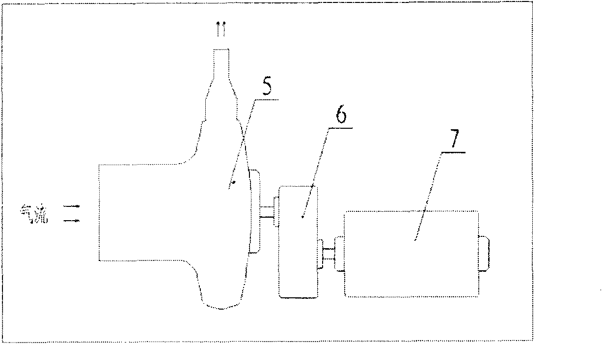
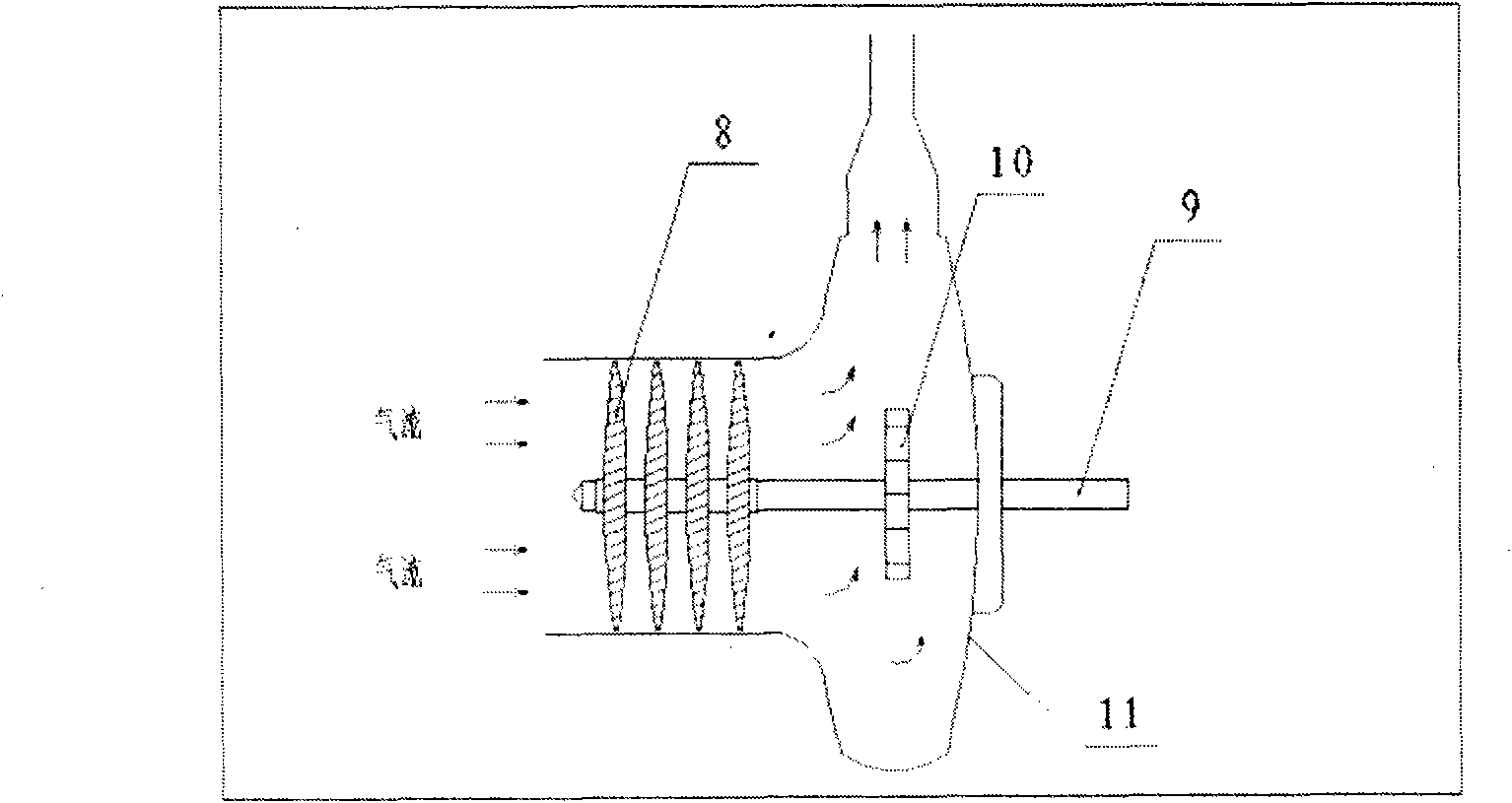
[0038] In order to explain the working principle of the pneumatic jet engine in detail and explain the functions of each part clearly, the following is divided into two parts:

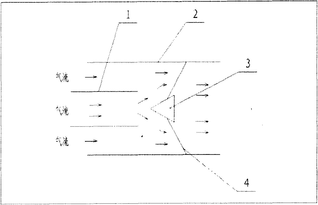
[0039] 1. Throat ( figure 1 ):

[0040] The structure of the throat is as figure 1 shown. Its working principle is divided into two working modes, one is internal pneumatic mode, and the other is external pneumatic mode. The two working modes are explained separately below. (1) Inner aerodynamic mode: Inner aerodynamic mode is that the central tube provides power air flow, and the air duct between the central tube and the outer tube is used as the main air duct. When the central tube of the throat pipe has airflow jetting from left to right at high speed, the airflow will form a fan airflow at the outlet of the central tube, which will block the space between th...


PUM


Abstract

The invention adopts a novel design idea and provides a pneumatic jet engine for an aircraft. The engine provided by the invention abandons the working mode of the existing jet engine fundamentally and adopts a technical scheme named as a throat tube by the inventor, so that the jet engine provided by the invention is pneumatically started and is operated without blocking an air suction duct so as to improve the flight speed and cruise efficiency of the aircraft. Therefore, the jet engine provided by the invention solves the problems that the existing jet engine is short of power at high speed, short in service life and low in operating efficiency, and important parts are not easy to produce and the like.

Description

Technical field [0001] The invention relates to the aspect of national defense and military affairs, belongs to the field of aerospace and aerospace, and in particular provides a high-speed jet engine for aircraft. Background technique [0002] There are currently two types of jet engines in the world, one is a turbofan engine and the other is a turbojet engine. Although there are two types, they are basically the same in terms of working principles. The core is that the combustion chamber and the turbofan system cooperate with each other to work. The static thrust produced by such an engine is relatively large, but the dynamic relative thrust will gradually weaken as the speed increases until it is zero. With the continuous development of modern military technology, if it can implement combat faster than any aircraft in other countries, then the control of air supremacy will be more beneficial. This requires faster flying speeds of fighter jets or other aircraft. [0003...

Claims


Application Information

Patent Timeline
Patent Type & Authority Applications(China)
IPC IPC(8): F02C7/04F02C7/26
Inventor 万学先
Owner 万学先
Learn More