Design method of cross cylindrical roller bearing with two right-angle roller paths

A technology of crossed cylindrical rollers and cylindrical rollers, applied in the field of bearing design, can solve the problems of large radial bearing capacity, difficult machining, and many machining passes, and achieve the improvement of axial bearing capacity and overturning moment, Improving the radial bearing capacity and the effect of improving the radial bearing capacity

Active Publication Date: 2012-07-25
洛阳轴研科技有限公司
View PDF3 Cites 6 Cited by
  • Summary
  • Abstract
  • Description
  • Claims
  • Application Information

AI Technical Summary

Problems solved by technology

[0008] Since the outer ring of the single-raceway crossed cylindrical roller bearing has a two-half structure, the outer ring of the two-half structure has many machining passes and is difficult to machine, especially the two halves of the split The outer ring of the structure can only be machined with the right-angle raceway after being bolted together, so the machining accuracy of the right-angle raceway is difficult to keep consistent with the machining accuracy of the right-angle raceway of the inner ring, which affects the single-roller Therefore, single-race crossed cylindrical roller bearings are mostly used in workplaces with large axial loads and small radial loads;
[0009] When single raceway crossed cylindrical roller bearings are used in occasions with large radial loads, their radial load capacity is often insufficient, because the split-type two-half structure outer ring and single raceway It does not have a large radial bearing capacity;
[0010] When the size of the matching main engine is large, it is difficult to guarantee the structural size of the shaft and bearing seat matched with the single-raceway crossed cylindrical roller bearing, and the installation of the single-raceway crossed cylindrical roller bearing is also relatively difficult;

Method used


Image

  • Design method of cross cylindrical roller bearing with two right-angle roller paths
  • Design method of cross cylindrical roller bearing with two right-angle roller paths
  • Design method of cross cylindrical roller bearing with two right-angle roller paths

Examples


Embodiment Construction

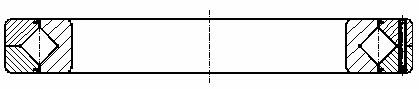
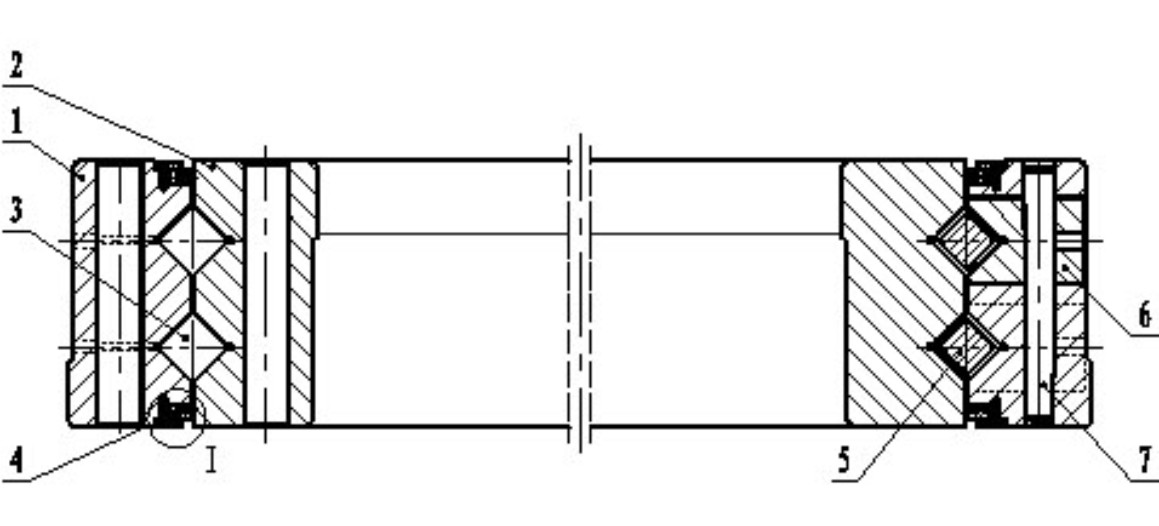
[0043] The present invention relates to a design method of crossed cylindrical roller bearings with two right angle raceways. Compared with single raceway crossed cylindrical roller bearings, the crossed cylindrical roller bearings with two right angled raceways are called double raceway crossed cylindrical roller bearings. sub bearings.

[0044] Double raceway crossed cylindrical roller bearings include outer ring, inner ring, cylindrical rollers and spacers, which is similar to the basic structure of single raceway crossed cylindrical roller bearings. The inner diameter end surface of the two-half structure of the outer ring has a right-angle raceway, and the outer diameter end surface of the inner ring is also a right-angle raceway. The right-angle raceway of the outer ring and the right-angle raceway of the inner ring have the same structural shape and correspond to each other to form a square raceway. The square raceway is equipped with an odd number of cylindrical roller...


PUM


Abstract

The invention provides a design method of a cross cylindrical roller bearing with two right-angle roller paths. An outer ring (1) is designed in an integral structure by a split type dual-half structure. The outer ring comprises two right-angle roller paths, an outer mounting hole (1.1), an outer hoisting thread hole (1.2), a lubricating oil hole (1.3), a plunger (6) and a conical pin (7). An inner ring comprises two right-angle roller paths, an inner mounting hole (2.1) and an inner hoisting thread hole (2.2). A cylinder roller (3) and an isolation block (5) are configured in the corresponding roller paths of the inner ring and the outer ring. Sealing is carried out through a sealing assembly (4), so that the problems of a plurality of machining processes, poor mounting condition, poor sealing, no lubrication and the like in a cross cylindrical roller bearing with a single roller path can be solved. Therefore, the axial bearing force and the overturn moment can be ensured, and simultaneously the radial bearing force is greatly improved.

Description

[0001] technical field [0002] The invention belongs to the technical field of bearing design, and in particular relates to a design method of a cross cylindrical roller bearing with two right-angle raceways. [0003] Background technique [0004] figure 1 It is a schematic diagram of the structure of a single raceway crossed cylindrical roller bearing. figure 1 It is a plan view, so it cannot show the cross arrangement of cylindrical rollers in the inner and outer ring raceways. [0005] According to the standard JB / T6636, the single raceway crossed cylindrical roller bearing is composed of outer ring, inner ring, cylindrical rollers and spacer blocks. A right-angled raceway is also provided. The right-angled raceway of the outer ring and the right-angled raceway of the inner ring have the same structural shape and correspond to each other to form a square raceway. The square raceway is equipped with an odd number of cylindrical rollers. The diameter of the cylindrical ...

Claims


Application Information

Patent Timeline
IPC IPC(8): F16C19/38F16C33/58F16C33/64F16C33/66F16C33/78
Inventor 张阗李雪飞李立王玉国张亚辉
Owner 洛阳轴研科技有限公司
Why Eureka
Try Eureka