
Load-bearing adjustable zero-stiffness electromagnetic vibration isolator and control method thereof

A zero-stiffness, vibration isolator technology, applied in the field of load-bearing adjustable zero-stiffness electromagnetic vibration isolators and its control, can solve the problems that the vibration isolation system deviates from the quasi-zero stiffness working state and cannot achieve the vibration isolation effect

Inactive Publication Date: 2012-07-25
HUNAN UNIV
View PDF5 Cites 51 Cited by
  • Summary
  • Abstract
  • Description
  • Claims
  • Application Information

AI Technical Summary

Problems solved by technology

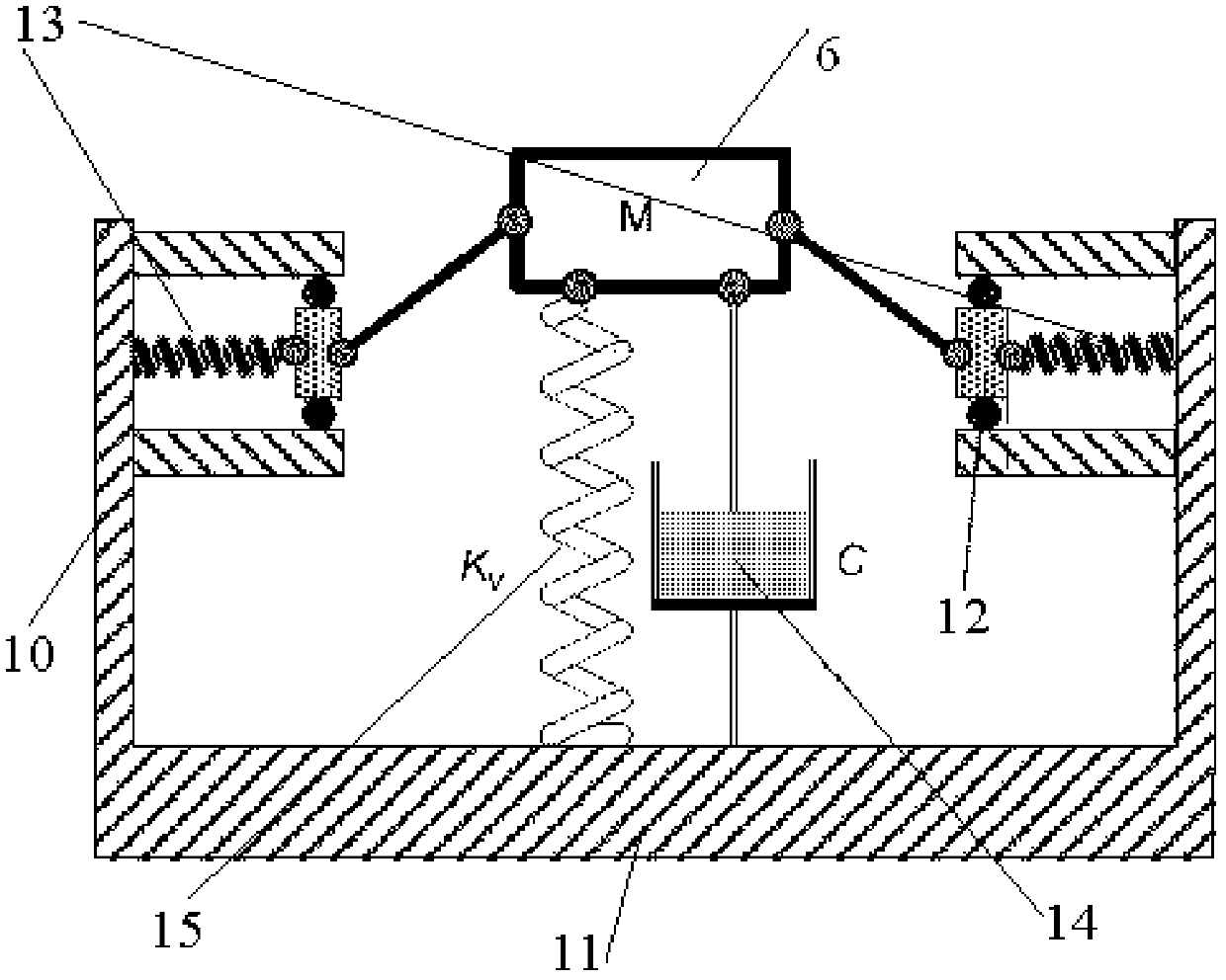
[0003] The structure of the existing quasi-zero stiffness vibration isolation system is shown in figure 1 , its defect is that the system parameters are only designed for a specific load-bearing weight. If the load-bearing weight changes, the vibration isolation system will deviate from the original quasi-zero stiffness working state, and it will not achieve a good vibration isolation effect; in some applications Occasions (such as car seats), the load-bearing weight changes, and this vibration isolation system cannot automatically adjust the stiffness according to the change of the load-bearing weight

Method used


Image

  • Load-bearing adjustable zero-stiffness electromagnetic vibration isolator and control method thereof
  • Load-bearing adjustable zero-stiffness electromagnetic vibration isolator and control method thereof
  • Load-bearing adjustable zero-stiffness electromagnetic vibration isolator and control method thereof

Examples


Embodiment Construction

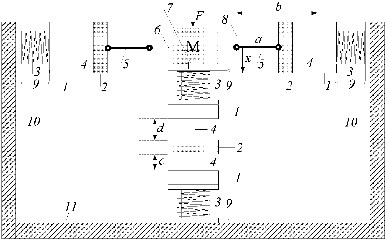
[0035] Such as figure 2 As shown, an embodiment of the present invention includes a vibration isolation device 6, a group of electromagnetic springs in the vertical direction, and two groups of electromagnetic springs in the horizontal direction. The outer frame 10 is installed on the left and right sides of the base 11, and the control circuit 9 is also included. The electromagnetic spring includes a set of electromagnets and two permanent magnets. The right side of the vibration isolation device 6 is connected to the first permanent magnet of the right horizontal electromagnetic spring through a connecting rod, and the first permanent magnet of the right horizontal electromagnetic spring is The magnet is connected with the second permanent magnet through the guide bar 4, and the second permanent magnet is connected with the electromagnet, and the electromagnet is fixed on the right outer frame 10; the electromagnetic spring in the vertical direction includes two groups of el...


PUM


Abstract

The invention discloses a load-bearing adjustable zero-stiffness electromagnetic vibration isolator and a control method thereof. An electromagnetic spring of the vibration isolator in the perpendicular direction is composed of three permanent magnets and two groups of controllable direct current electromagnets, two magnets have opposite polarity and generate repulsive force, and stiffness of theelectromagnetic spring can be adjusted by changing and controlling current. An electromagnetic spring of the vibration isolator in the horizontal direction is composed of two groups of symmetrically distributed electromagnetic springs, and stiffness of the electromagnetic spring can be adjusted by changing and controlling current. When the system load-bearing weight is changed, the stiffness of the perpendicular electromagnetic spring and the stiffness of the horizontal electromagnetic spring are led to meet a certain proportional relationship by adjusting and controlling current so that stiffness of the system at the balance position can be zero. When a vibration isolation device is in small vibration near the balance position, dynamic stiffness is very small, and natural frequency of the whole system is very low so that the vibration isolator can achieve wide-range frequency vibration isolation and has good low frequency vibration isolation effect. In addition, the vibration isolator is compact in structure, light in weight and convenient to control.

Description

technical field [0001] The invention relates to a vibration isolation system, in particular to a load-bearing adjustable zero-stiffness electromagnetic vibration isolator and a control method thereof. Background technique [0002] With the development of society and the improvement of quality of life, people have higher and higher requirements for vibration isolation technology of some equipment. However, those bad vibrations have a great negative impact, affecting people's work, making people uncomfortable, or causing other problems. For example, the requirements for high comfort of automobiles, the protection of highly precise measuring instruments carried by aerospace vehicles during rocket launches, and the vibration and noise reduction of underwater navigation submarines, etc., all have increasingly stringent requirements for vibration isolation technology. Traditional linear system isolators are only (ω,ω n are the excitation frequency and the natural frequency of ...

Claims


Application Information

Patent Timeline
Patent Type & Authority Applications(China)
IPC IPC(8): F16F15/03
Inventor 徐道临张敬周加喜张月英
Owner HUNAN UNIV
Learn More