Clutch and reversing device

A reversing device and gear technology, applied in the field of clutches, can solve problems such as large radial and axial dimensions, inability to rotate by hand, unsuitable for clutches, etc., and achieve long service life, ensure safety, and have no joint noise Effect

Active Publication Date: 2012-07-25
徐彬
View PDF6 Cites 1 Cited by
  • Summary
  • Abstract
  • Description
  • Claims
  • Application Information

AI Technical Summary

Problems solved by technology

However, some working machines (such as hoisting machines, winches, etc.) are in a braking state when they stop, and cannot be turned by hand, so it is not suitable to use
[0009] Friction clutches have disc type and conical type. Although there are single-plate, multi-plate, dry and wet types in the structure of this type of clutch, and the manipulation methods include mechanical, electromagnetic or hydraulic and pneumatic, etc., but the clutches of this type The radial and axial dimensions are large, and it is difficult to select a suitable product under the premise of requiring a simple and compact structure. In addition, the mechanical device used for field work is not suitable for using electric, hydraulic, and pneumatic clutches.

Method used


Image

  • Clutch and reversing device
  • Clutch and reversing device
  • Clutch and reversing device

Examples


Embodiment Construction

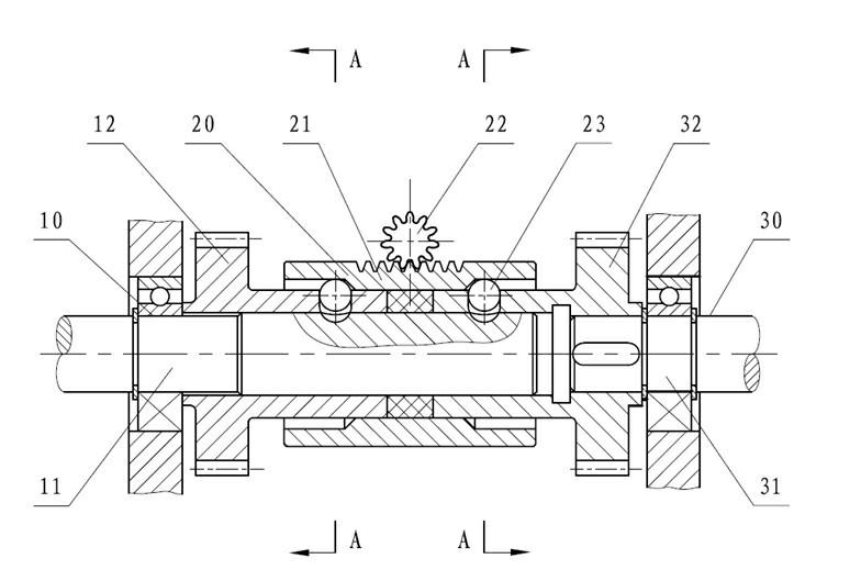
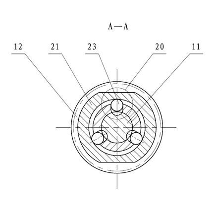
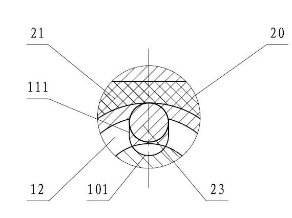
[0036] Such as Figure 1-7 As shown, the device includes an input shaft component 10, a clutch and reversing component 20, and an output shaft component 30. A clutch and reversing component 20 is installed between the input shaft component 10 and the output shaft component 30 to form a clutch and reversing device, wherein The bridge shaft component connected with the input shaft component 10 and the output shaft component 30 is not shown in the figure; the input shaft component 10 is composed of an input shaft 11 and an input shaft gear 12, and the output shaft component 30 consists of an output shaft 31 and an output shaft gear 32 The clutch and reversing part 20 is composed of a sliding sleeve 21, a gear shaft 22, and a steel ball 23. The input shaft gear 12 and the output shaft gear 32 are sleeved on the input shaft 11, and the output shaft gear 32 is connected to the output shaft with a flat key 31 is connected as a whole, the input shaft 11 and the output shaft 31 are coax...


PUM


Abstract

The invention discloses a clutch and reversing device comprising an input shaft part, a clutch and reversing part, an output shaft part, etc. The clutch and reversing device is characterized in that when a clutch slippage sleeve is arranged between an input shaft gear and an output shaft gear, steel balls in drill holes radially and uniformly distributed in sleeves of the input shaft gear and the output shaft gear are all positioned in countersink sections of an inner hole of the slippage sleeve, when an input shaft rotates, the steel balls are extruded out of input shaft ball sockets, and the input (or output) gear idles on the input shaft so as to realize the separation of a clutch. When the slippage sleeve moves towards the right side, transition inclined planes between the inner hole and countersinks of the slippage sleeve are gradually pressed down by the steel balls, then the steel balls are pressed and enter a circle of radially and uniformly distributed ball sockets at the right side of the input shaft, the input shaft and the output shaft gear are wedged into a whole, and an output shaft rotates along with the input shaft in the same direction; and the output shaft can rotate reversely when the slippage sleeve moves towards the left side. The clutch and reversing device can realize separation and reversion under the work condition of high rotation difference.

Description

Technical field [0001] The invention relates to a clutch, in particular to a clutch and reversing device. Background technique [0002] In some mechanical devices, small internal combustion engines (small gasoline engines or small diesel engines) are used as the source of power. The working machinery requires low speed and large output torque. The structure of this type of machinery is generally composed of internal combustion engines, large reduction ratio reducers and working machinery. composition. [0003] When the internal combustion engine is started, it must be started with no load. A clutch must be provided in the device to disconnect the internal combustion engine from the subsequent working devices; after the internal combustion engine is started, the working machine needs to be engaged, so that the power of the internal combustion engine can be transmitted to the working machine. [0004] The working machinery requires the function of forward and reverse operation. Th...

Claims


Application Information

Patent Timeline
Patent Type & Authority Applications(China)
IPC IPC(8): F16H37/00
Inventor 徐彬邱正兴
Owner 徐彬
Why Eureka
Try Eureka