Mechanical hydraulic compound drive gearbox
A composite transmission and mechanical hydraulic technology, applied in the field of gearboxes, can solve the problems such as the sun shaft and the ring gear shaft cannot reliably maintain concentric rotation, the stable rotation of the sun shaft and the ring gear shaft is not guaranteed, and the transmission efficiency of the transmission device is unstable. , to achieve the effect of good climbing performance and starting performance, light weight and easy installation
- Summary
- Abstract
- Description
- Claims
- Application Information
AI Technical Summary
Problems solved by technology
Method used
Image
Examples
no. 1 example
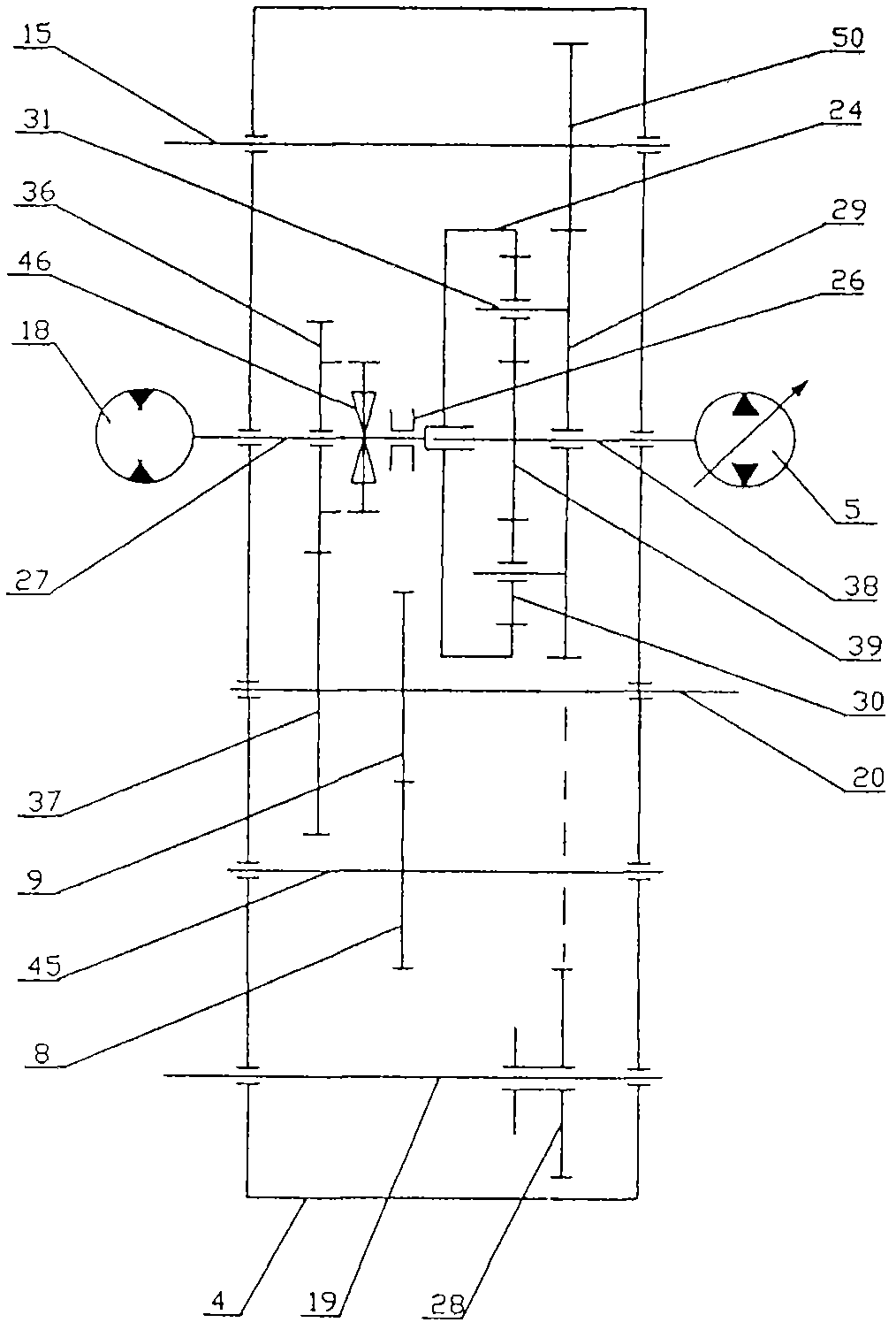
[0023] figure 1 This is a schematic diagram of the structure of the first embodiment of a mechanical-hydraulic composite transmission gearbox for the patent application of the present invention. The mechanical-hydraulic composite transmission gearbox of the present application is installed in a special vehicle transmission system similar to a road sweeper, and the special vehicle uses the accelerator pedal to control the engine speed when moving around; The operating speed of the special vehicle is driven by the mechanical hydraulic compound transmission gearbox with the foot pedal of the variable hydraulic pump 5 . like figure 1Shown: a mechanical-hydraulic composite transmission gearbox, on the box body 4 are installed an input shaft 19, a bridge shaft 45, a travel output shaft 20, an operation output shaft 15, a variable hydraulic pump 5, a hydraulic motor 18 and a planetary gear mechanism , on the input shaft 19, the transfer gear A28 is fitted through the spline, the br...
no. 2 example
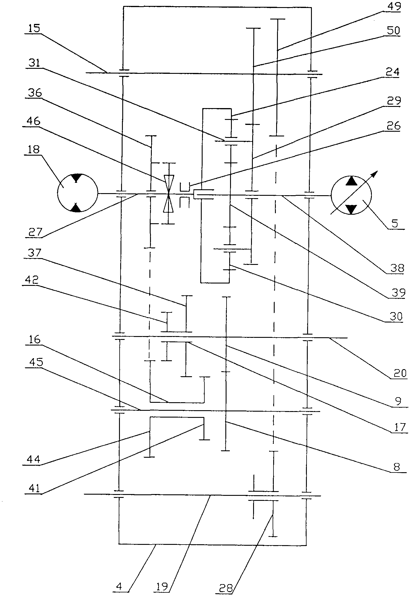
[0027] figure 2 This is a schematic diagram of the structure of the second embodiment of a mechanical-hydraulic composite transmission gearbox for the patent application of the present invention. like figure 2 Shown: a mechanical-hydraulic compound transmission gearbox, on the basis of the first embodiment, the set transfer gear B49 and the transfer gear C50 are respectively fixed on the operation output shaft 15, and the splitter can be moved by the fork through the spline. The moving gear A28 moves on the input shaft 19, and makes the transfer gear A28 mesh with the transmission bridge gear A8 or the transmission transfer gear B49, and the transfer gear C50 meshes with the transmission planet carrier gear 29; The transition gear B44 and the transition gear D41 are assembled into a The joint gear A16 is slidably sleeved on the bridge shaft 45 with the bearing fixed position, the transition gear A36 meshes with the transmission transition gear B44, and the transition gear C...
no. 3 example
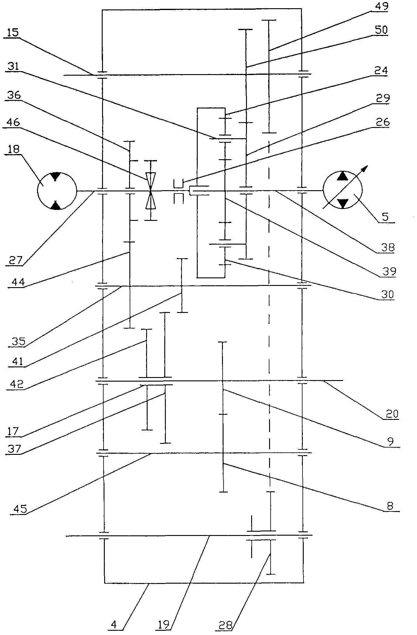
[0036] image 3 This is a schematic diagram of the structure of the third embodiment of a mechanical-hydraulic composite transmission gearbox for the patent application of the present invention. like image 3 Shown: a mechanical-hydraulic compound transmission gearbox, on the basis of the second embodiment, a transition shaft 35 is also installed on the gear box 4, and the transition gear B44 and the transition gear D41 are respectively fixed and sleeved on the transition shaft 35.
[0037] The transmission principle and operation method of this embodiment are similar to those described in the second embodiment, and will not be repeated here.
PUM
 Abstract
Description
Claims
Application Information
 - R&D
- Intellectual Property
- Life Sciences
- Materials
- Tech Scout
- Unparalleled Data Quality
- Higher Quality Content
- 60% Fewer Hallucinations
Browse by: Latest US Patents, China's latest patents, Technical Efficacy Thesaurus, Application Domain, Technology Topic, Popular Technical Reports.
© 2025 PatSnap. All rights reserved.Legal|Privacy policy|Modern Slavery Act Transparency Statement|Sitemap|About US| Contact US: help@patsnap.com


