Rotor displacement measurement device and method for planar motor

A plane motor, displacement measurement technology, applied in the direction of measuring devices, electrical devices, opto-mechanical equipment, etc., can solve the problems of the grating scale surface being polluted, the use environment is high, and the measurement accuracy is greatly affected by the environment.

Active Publication Date: 2012-07-25
TSINGHUA UNIV +1
View PDF10 Cites 23 Cited by
  • Summary
  • Abstract
  • Description
  • Claims
  • Application Information

AI Technical Summary

Problems solved by technology

In patent 200880111964.6, two-dimensional gratings are used to measure the motion of planar motors. It is necessary to install a larger area of ​​planar gratings on the planar motors to generate optical signals with displacement information for communication with optical sensors. The scale surface is polluted; patent 201110040403.5 uses a grating sensor to detect the movement position in two directions, and each movement direction needs to install a main scale that meets the rang

Method used


Image

  • Rotor displacement measurement device and method for planar motor
  • Rotor displacement measurement device and method for planar motor
  • Rotor displacement measurement device and method for planar motor

Examples


Embodiment

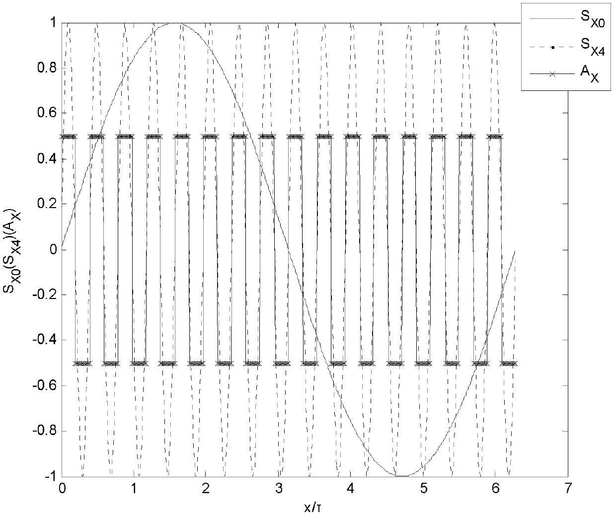
[0070] in m x = m y =4. Take the magnetic field pole distance τ=35.35mm as an example, according to the calculation formula for the maximum number of spatial frequency multiplication operations, select n X =n Y =4, implement the device and method of the present invention.

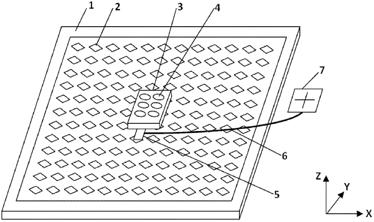
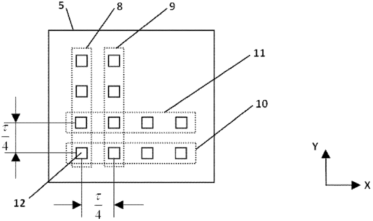
[0071] The device reference figure 1 The planar motor of the present invention is a moving-coil planar motor including a stator 1 and a mover 3 on the stator 1, the stator 1 includes a magnetic steel array 2, and the lower surface of the mover 3 is provided with a coil array 4; The displacement measuring device includes a probe 5, two groups of sine sensors, two groups of cosine sensors, a signal conducting line 6 and a signal processing circuit 7; Sinusoidal magnetic field area; the two groups of sine sensors include the x-direction sine sensor group 8 and the y-direction sine sensor group 10, and the two groups of cosine sensors include the x-direction cosine sensor group 9 and the y-direction cosine ...


PUM


Abstract

The invention provides a rotor displacement measurement device and method for a planer motor. According to the method, two sets of magnetic flux density sensors are respectively and uniformly distributed in a field pole polar distance tau in two mutually perpendicular moving directions of a sine magnetic field area formed by a stator magnetic steel array on the planer motor, sampled signals of the four sets of sensors are subjected to frequency multiplication operation by a signal processing circuit respectively to obtain four subdivided signals, zero crossing points of the four subdivided signals are detected to generate two orthogonal pulse signals, pulses of the two orthogonal pulse signals are counted respectively and the phase differences of the two orthogonal pulse signals are detected respectively. According to the invention, based on the magnetic field information of the planar motor, the magnetic field space tau is subdivided to realize the long-travel high-accuracy rotor displacement of the planar motor. Through adoption of the device and method disclosed by the invention, the problems caused by the requirements of long travel and high accuracy that calculation methods are complicated or hardware is inconvenient to install and the total cost of a measurement device is high can be solved.

Description

technical field [0001] The invention relates to a mover displacement measuring device and method of a planar motor with a sinusoidal magnetic field model, in particular to a subdivision displacement measuring device and an algorithm with a large stroke and high resolution. Background technique [0002] In two-dimensional positioning processing devices, especially modern semiconductor micro-processing equipment and other ultra-precision processing equipment, high-precision motion is usually realized by planar motors. Due to the advantages of fast response, high sensitivity and simple structure, planar motors have attracted extensive attention in both academia and industry. Patent 201110045692.8, patent 200910029368.X, and patent 200910088894.3 describe several planar motors with different structures in detail. [0003] At present, optical measurement methods such as gratings and laser interferometers are often used to detect the position of the mover of planar motors. In pa...

Claims


Application Information

Patent Timeline
IPC IPC(8): G01B7/02
CPCG01B7/02G01D5/2013G03F7/70758G01B7/30
Inventor 胡金春朱煜尹文生陈龙敏杨开明张鸣徐登峰穆海华胡楚雄刘召
Owner TSINGHUA UNIV
Why Eureka
Try Eureka