Digital domain balanced detecting method and device for optical fiber gyroscope

A fiber optic gyroscope and detection device technology, applied in the field of communication, can solve the problems of data zero-bias fluctuation and zero-bias stability reduction, and achieve the effect of improving zero-bias stability

Inactive Publication Date: 2012-07-25
PEKING UNIV
View PDF4 Cites 11 Cited by
  • Summary
  • Abstract
  • Description
  • Claims
  • Application Information

AI Technical Summary

Problems solved by technology

[0032] However, in the existing angular velocity measurement methods, the existing Faraday magnetic field effect, drift or other low-frequency noise caused by temperature fluctuations, as well as the polarization evolution in the fiber optic gyroscope and the flicker noise of the detector will lead to fluctuations in the zero bias of the data That is, the bias stability is reduced

Method used


Image

  • Digital domain balanced detecting method and device for optical fiber gyroscope
  • Digital domain balanced detecting method and device for optical fiber gyroscope
  • Digital domain balanced detecting method and device for optical fiber gyroscope

Examples


Embodiment Construction

[0059] In the following description, for purposes of explanation, numerous specific details are set forth in order to provide a thorough understanding of one or more embodiments. It may be evident, however, that these embodiments may be practiced without these specific details. In other instances, well-known structures and devices are shown in block diagram form in order to facilitate describing one or more embodiments.

[0060] Various embodiments according to the present invention will be described in detail below with reference to the accompanying drawings.

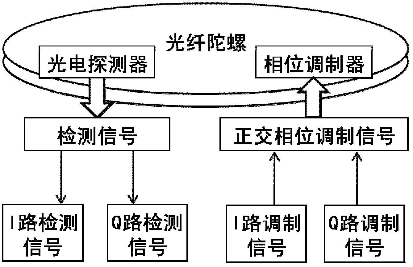
[0061] image 3 A schematic diagram of the method in the present invention is shown. Such as image 3 As shown, the phase modulation of the fiber optic gyroscope is carried out by using I and Q two-way quadrature signals, that is, the linear combination of the I and Q two-way quadrature signals is used as the input of the fiber optic gyroscope, and the phase of the input to the fiber optic gyroscope on the modulato...


PUM


Abstract

The invention provides a digital domain balanced detecting method for an optical fiber gyroscope, which comprises the following steps of: applying a phase modulation signal to a phase modulator, wherein the phase modulation signal is obtained after a sinusoidal signal and a cosine signal which have the same modulation frequency are linearly combined; using the applied sinusoidal signal as an I-path reference signal and carrying out derivation on the I-path reference signal to obtain a Q-path reference signal; respectively carrying out coherent processing on a signal output by the optical fiber gyroscope and the I-path reference signal and the Q-path reference signal so as to obtain an I-path detection signal and a Q-path detection signal; respectively demodulating the I-path and Q-path detection signals to obtain an I-path angular velocity measured value and a Q-path angular velocity measured value; and according to a preset linear formula, combining the I-path and Q-path angular velocity measured values to obtain a measured value of an angular velocity to be measured, wherein the preset linear formula is predetermined according to the linear combination of the applied sinusoidal signal and cosine signal. Due to the utilization of the method, the bias stability of the optical fiber gyroscope can be improved.

Description

technical field [0001] The present invention relates to the technical field of communication, and more specifically, to a digital domain balance detection method and device of an optical fiber gyroscope. Background technique [0002] A gyroscope is a rotational sensor used to measure the rotational angular velocity of the carrier on which it is mounted. Gyroscopes are widely used in the guidance of various aircraft and weapons, and various precision measurements in industry and military. There are three types of common gyroscopes: mechanical gyroscopes, laser gyroscopes, and fiber-optic gyroscopes (Fiber-optic gyroscope, FOG). The latter two are optical gyroscopes. Optical gyroscopes have the characteristics of compact structure and high sensitivity, but their stability is not as good as some modern mechanical gyroscopes. Due to the needs of the application, the new gyroscope should have high sensitivity and stability, low cost and power consumption, and small size. [0...

Claims


Application Information

Patent Timeline
Patent Type & Authority Applications(China)
IPC IPC(8): G01C19/72
Inventor 王子南杨易李永啸张振荣李正斌
Owner PEKING UNIV
Why Eureka
Try Eureka